
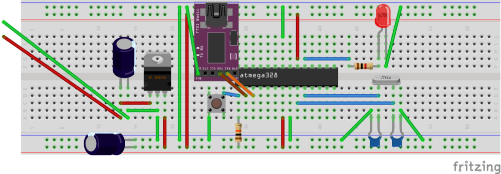
This project will consist of setting up at Atmega 328 on a Breadboard. This will be mostly compatible with the Arduino Uno. This project is for those who are minimalists, or those who want to learn more about how the external circuitry works on a microprocessor. I created the image below with Fritzing, and we will be using this as an example:
Disclaimer: Although I believe this information to be accurate, the information is provided “as-is”. You are responsible for ensuring the accuracy, safety issues, etc. If you find corrections that need to be made, please let me know.
Components for Setting up the Atmega 328 on a Breadboard
- 1 Breadboard and assortment breadboard jumpers
- 1 Power Supply (recommended 7 to 12 VDC) 500ma should be more than sufficient.
- 1 Atmega328-PU processor
- 1 FTDI Basic programmer (Optional but handy)
- 2 capacitors (10 microfarad)
- 2 capacitors (22 picofarad)
- 1 resonator (16MHz)
- 1 resistor (10K ohm)
- 1 resistor (1K ohm)
- 1 LED indicator
- 1 7805 Voltage regulator (5v)
- 1 Pushbutton (for reset circuit)
Step 1 — Power your Breadboard
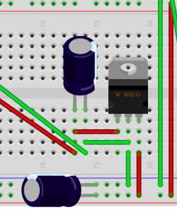
There are many ways to power up your breadboard. Breadboard power supplys can be purchased that are already regulated and filtered. Another option is to power the breadboard with the VCC pin of the FTDI programmer if enough current is available. In this example, we will be bringing in a 7 to 12 VDC supply that we can purchase at most any thrift store for under $1. We won’t need a lot of current for this simple circuit, so 500ma should be more than sufficient.
In the circuit below, we will bring in power from this supply on the left. Add a 10 microfarad capacitor across the + and -, but be careful when using electrolytic capacitors because polarity is important. The long lead is usually the +, and the short lead is -. This should be marked on the capacitor as well. After the capacitor, the + will go to the left pin of the 7805 voltage regulator, and – to the center pin. This center pin will also go to the – of our breadboard power rail, and the right pin will go to + on the brreadboard power rail. Add another 10 microfarad capacitor across the breadboard power rails after the regulator for further filtering. We will also jumper the power rails together as shown on the breadboard.
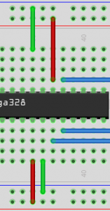
Step 2 — Power the Atmega 328 Microprocessor
 Step 2 — Power the Atmega 328 Microprocessor
Please take a look at the pinout of the atmega328 microprocessor. You can search google for a pinout diagram, but at the time of this writing, a good diagram is shown at this link. http://www.hobbytronics.co.uk/image/data/tutorial/arduino-hardcore/atmega328-arduino-pinout.jpg You may want to print the pinout image for future reference. We need to connect our + rail to pins 7 and 20 on the chip as shown. The – on our power rail will connect to pins 8 and 22.
For now, we’ll just connect the red and the green lines that are shown. We’ll connect the blue lines later.
Step 3 — The resonator circuit
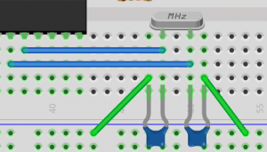
Some of the processors have an 8 MHz resonator built in that we can use on the Atmega328. I’ve found this to be somewhat unstable though, and we must make changes to the chip’s fuses to enable the internal resonator. In this circuit, we will use an external 16 MHz oscillator. This will be our “clock” that will control the speed at which the chip will process information. The resonator will be across pins 9 and 10, then each leg of the resonator will go through a 22 picofarad capacitor, which is then goes to ground (-).
Step 4 — The reset circuit
 eset circuit
Pin 1 (just to the left of the notch of the chip) is our reset pin. We need to hold this pin in a high state with a 10k resistor. When we press the push button pin 1 will be at ground potential, and the processor will reset. After we press the button, some current will flow through the resistor, but with a 10K resistor, this is only 5 microamps. When we release the pushbutton, pin 1 has a very high input impedance, so pin 1 will be at the 5v level through the 10K resistor. For now, we will just connect the resistor, pushbutton, green, and blue wire as shown.
Step 5 — The LED circuit
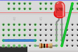 Step 5 — The LED circuit
To test our circuit later on with the blink example, we will want to connect an LED indicator. Pin 19 of the chip (Digital pin 13 in software) will go through a 1K resistor. We’ll connect this 1K resistor to the + side of the LED. The + side of the LED usually has the longest lead. We then connect the – side of the LED (short lead) to ground.
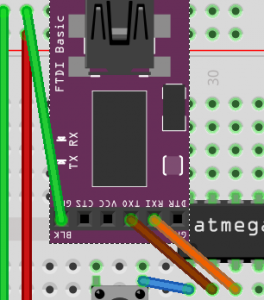
Step 6 — Connect the FTDI programmer
 DI programmer
The FTDI programmer is optional, but it does make this circuit easier to program. Otherwise, we would have to remove the Atmega 328 to place it on an Arduino Uno board for programming, then move the chip back onto our breadboard. The FTDI programmer will allow us to program the chip while it is in place as long as the chip has a bootloader on it. If you removed this module from an Arduino for this experiment, then chances are that it does have the bootloader set up. Connect the Receive pin (chip’s pin #2) to transmit of the FTDI Programmer. Connect the transmit pin of the Atmega 328 (chip’s pin #3) to the receive pin of the FTDI programmer. Then connect ground of the FTDI programmer to ground (-) on the breadboard.
Step 7 — Upload the Blink example
In your Arduino IDE open the Blink example. When you are ready to upload, press the upload button in the IDE, and quickly press the reset button simultaneously. When your IDE shows “Uploading”, release the reset button.
Extra capacitors
To improve stability, place a .1uF capacitor across pins 7 and 8. This is a noise bypass filter. Additionally, you can place a .1uF capacitor between DTR on your programmer and pin 1 on the processor. This should cause your processor to automatically reset when you upload your sketch.
— Ricky Bryce