
Introduction to IOT2020
In this document, we will setup and configure the Siemens Simatic IOT2020 processor to be able to accept a simple “Blink” program using the Arduino IDE. Although I believe the information in this document to be accurate, you assume all responsibilities for safety, and must verify the information before utilizing it in any way. Please let me know if you find any errors in this procedure.
The Siemens IOT2020 is a gateway device that allows you to program I/O as you would an Uno board. It also has a Linux based operating system, which gives more capability than a standard Atmega 328 processor. The setup is very simple. One of the problems I had when I first set up the board was that I was attempting to use the FTDI programmer to upload the sketch. The FTDI programmer works great for interfacing with the Linux operating system (via serial console), but I was only successful uploading the sketch through the Micro-USB interface once the operating system was installed.
Hardware
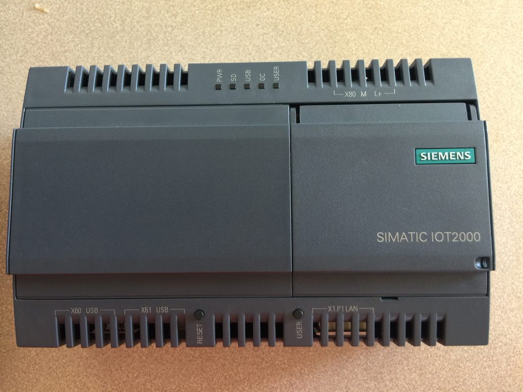
The IOT2020 has several status indicators: Power, SD Active, USB Power, Over Current, and a User light (similar to LED #13 on a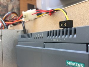 n Uno board) This module can be powered by 9 to 36 VDC according to the user manual. In my case, I’ve powered the module from a computer power supply unit using the 12V leads that would normally connect to the hard drive. You also have a RESET button, and a User button.
Here, I’ve already connected the power supply, but we will apply power later, after the SD card has been set up and a few connections have been made.
MicroSD Image
I used a 32 GB Sandisk Ultra Plus for this configuration, and downloaded the SD image from this address:
http://downloads.arduino.cc/iot2000/iot2000-example-image-iot2000-20170130142104.rootfs.img
The image is also available from Siemens website, and I would encourage you to search for the latest example image.
Once the image is downloaded, you will burn the image to your MicroSD card. You can use Win32 disk imager at this address:
https://sourceforge.net/projects/win32diskimager/
Or another option is to use Etcher:
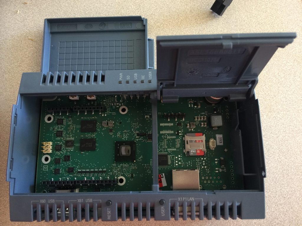
Once the MicroSD card has been set up, you can place it into your IOT2020. To open the door for the MicroSD slot, gently push the bracket toward the bottom of the module, then the bracket will swing upward. You can then place the MicroSD card into it’s holder, and re-position the bracket, and slide the bracket toward the top of the module to lock the MicroSD card into place.
Startup
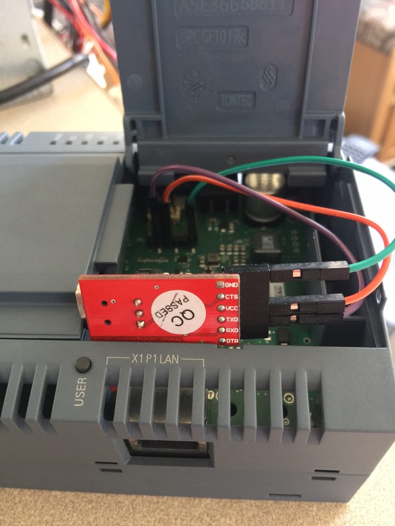
This next step is not necessary if you are just going to use the Arduino IDE, but it’s nice to have an FTDI programmer to see what is going on as the processor boots up. In my case, I have an FTDI programmer that I’ve set up for 3.3v. I’ve then connected GND to the right pin of the programming header… TX to RX, and RX to TX as shown. I didn’t plug the FTDI programmer directly into the board, because my cable is heavy, and I didn’t want to put much stress on the IOT2020’s board.
As long as the drivers are installed (and you have a good cable!!), You should be able to see the COM port of your FTDI programmer under Tools | Port in the Arduino IDE.
Next, I opened the Serial Monitor, and applied power to the IOT2020, and was able to watch the bootup process. Since the default IP address is 192.168,200.1, I need to change this. I closed the Serial Monitor, and connected with PUTTY (through the same COM port). I’m using Debian 8, so my com port was /dev/ttyUSB0. The login is “root” with no password.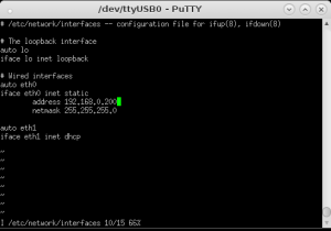
Then, I typed vi /etc/network/interfaces to change the IP as shown:
Then press the escape key, then :wq (colon w q) to write the file and quit the editor. You can then type “reboot” to reboot the IOT2020 if you wish to use SSH in the future over your network.
Programming
Next, I co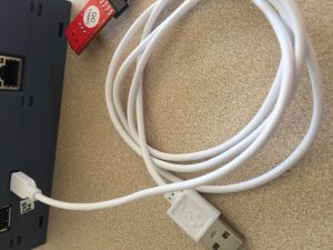 nnected my MicroUSB cable to the IOT2020. In Windows, you may need to install a driver for this module. Check “Device Manager” in the windows control panel to ensure your IOT2020 was recognized properly. Again, I’m using Debian 8, so I didn’t have a problem at all.
Make note of the COM port the IOT2020 appears on. We will need this later when we download the “Blink” Sketch. If your IOT2020 does not appear on your PC, please be sure you are using a good quality data cable as some cables can only be used for charging a device such as a phone.
In the Arduino IDE, we must add support for the Intel (R) Galileo Gen 2. Under Tools | Boards, go to your boards manager and search for, and install Intel (R) i586 support.
Under Tools | Boards, select the Intel (R) Galileo Gen 2. Under Tools | Port, select the COM port for your IOT2020.
Upload your sketch to the IOT2020, and you should see the USER indicator begin to blink.
— Ricky Bryce
If I have a sketch that makes use of ther Serial function (eg serial.println()) can I read that from the IoT2020 or would I need to loop the micro usb to the USB host port?
It’s my understanding that you can interface directly to ttyS0 (depending on your project), which is the Arduino pins 0 & 1 (tx and rx). Here is a site that I found that might help you with your project. https://www.hackster.io/paolo-carnovale/python-and-lorawan-on-the-siemens-iot2020-3ef9b5