
Introduction to Safety Relays
Safety relays help to ensure the safe operation of your equipment when used with safety devices such as light curtains, e-stops, and safety mats. Generally, they will provide protection from shorted safety circuits, and open safety circuits as well. The safety relay can even provide protection from a welded set of contacts.
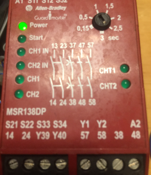
Undoubtedly there are many ways to connect a safety relay. This post will show just one example. In this case, I have an MSR138DP. I’ve applied 24v DC power to terminals A1 (+), and A2(-). This particular relay also has an off delay timer circuit built in. Always perform a safety analysis of your equipment to choose the correct relay type, and the correct wiring diagram that meets your needs based on your risk assessment.
Test Unit
Prior to writing this post, I’ve put together a small test unit for the relay. We have 2 ESTOPS. Both of which have two normally closed contacts. One set of contacts from an ESTOP are wired in series with one set of contacts on the second ESTOP. Likewise with the second set of contacts.
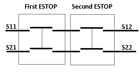
I’ve connected the first circuit (channel 1) to terminals S11 & S12. Likewise, I’ve wired the second set of contacts to S21 & S22.
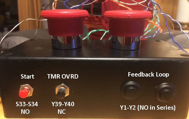
In addition, I’ve wired a start (reset) button to S33 & S34, which is normally open. Timer Override is Nomally closed, and wired to Y39 & Y40. At last, for the feedback loop, I have two normally open switches wired in series. I’ve connected the feedback loop to Y1 & Y2. I’ve also jumped S11 to S52.
Operation
Once the ESTOPS are pulled, we press the start button. As long as the Feedback loop is complete, the relay will energize. If I loose feedback, the relay will remain energized until I press the timer override button, or press an ESTOP.
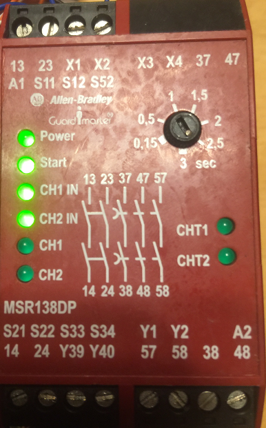
Let’s walk through this operation step by step. Here, I have the relay powered up.

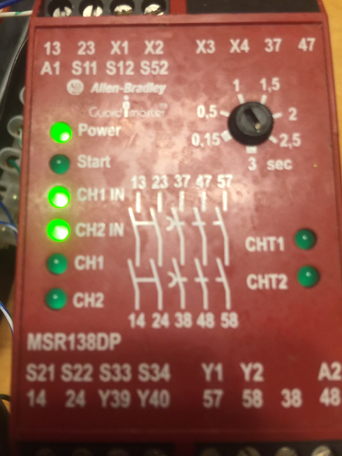
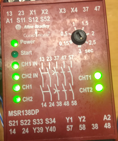
Next, I’ve pulled the ESTOPS. Notice that Channel 1 and Channel 2 are both made.
Thirdly, I’ll press the start button. Notice the start button lights up, but the channels have not engaged yet. This is because the feedback loop is not complete.
I’ll make the feedback loop now, and press, then release the start button.
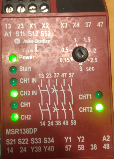
In this case, I’ve lost one of the ESTOP channels:
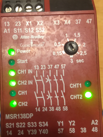
Notice that when I fix the channel, the channel’s output still has not engaged.
We must press an ESTOP, wait for the timeout, then start (reset) the relay again. At this point, the equipment will see the signal that both relays have engaged, and it’s OK for startup!
For more information, visit the main page at BryceAutomation.com!
— Ricky Bryce