Motion Axis Gearing allows one axis to follow another axis using a certain ratio of gearing. For example: A slave axis might follow a master axis, but at twice the speed, and cover twice the distance in a given amount of time. A practical application for this is two rollers that are transporting a sheet of paper or plastic. You will want to maintain tension on the product. By making the downstream roller a slightly higher speed than the upstream roller, you can achieve this tension. Other uses for Motion Axis Gearing (MAG) would be due to difference in the physical gearing of different pieces of equipment.
In this example, we will use our Virtual Axis. If you have not read up on the previous documents, be sure you have two virtual axis set up. Also familiarize yourself with how to use Motion Direct commands, and how to use the MAM command.
Remember, if you are using physical axis instead of virtual axis, be sure to take all safety precautions. This procedure will cause movement, and the movement could be unexpected.
Our goal in this demonstration is to move VirtualAxis2 at twice the speed of VirtualAxis1. Make sure you have already downloaded and are online in run mode. Right-Click VirtuaAxis2, and choose “Motion Direct Commands”.
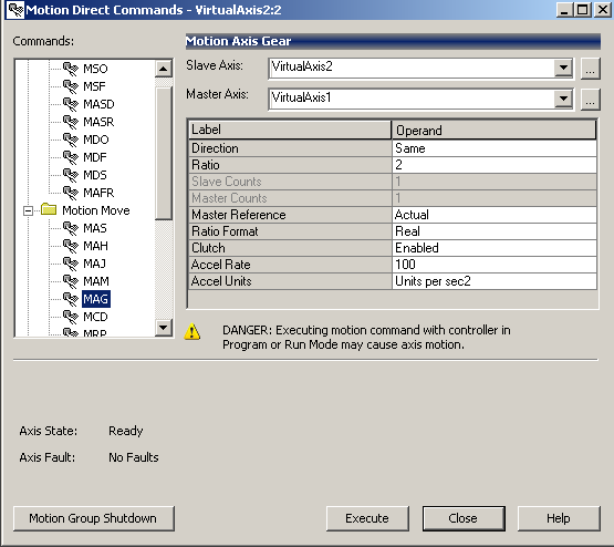
Configure the Motion Axis Gearing (MAG) command as follows:
The slave is VirtualAxis2. We are gearing this to VirtualAxis1, so that will be our master. The axis for this demonstration will move in the same direction. Our gear ratio is 2. Movement will take place from that actual position of Virtual Axis1 in this example. To keep things simple, our ratio format will be “Real”, which is 2 to 1. Otherwise we would have to calculate the encoder counts that we want the ratio to be based on. It’s a good idea to have the clutch enabled. If an actual master axis is moving when the gearing takes place the slave would accelerate very quickly, and would likely cause a position error. With the clutch enabled, we can set an acceleration for the slave to catch up with the master. This prevents an instantaneous lock, which would likely cause a position fault.
Press “Execute”, and the slave axis will be geared to the master.
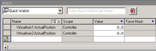
Next, you can go to View | Watch, and in the QuickWatch window, we can monitor the actual position of each axis before we execute the MAM command.
Next, we will attempt movement to test our gearing. We will do this with the MAM command on VirtuaAxis1. Right click on VirtualAxis1 to access it’s motion direct commands. We will choose the MAM command.
Configure the MAM command as follows:

We will move to the position of 1000 with a speed of 10. Here, I will leave the other fields at default. This should be slow enough so we can see the gearing take place.
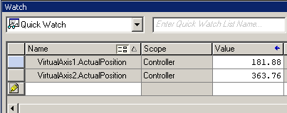
Now, press “Execute” and watch the position of each axis.
Here, we can see that VirtualAxis2 is moving twice as fast as VirtualAxis1.
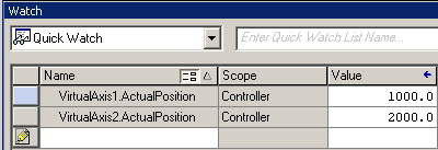
Finally, when VirtualAxis1 has reached it’s commanded position, VirtualAxis2 has moved twice the distance.
In conclusion, MAG command can be used in logic, just as the MAM command to automate the process of gearing and moving the axis.
— Ricky Bryce
The Motion Axis Move command will allow us to move an axis to a particular position. For example: If we know a product is at a certain position, we can move an axis to that particular location. There are two main types of moves: Absolute, and Incremental. With an absolute move, we can move the axis to a certain position with respect to the home position. In an incremental move, we can move the axis a certain number of units from our current location.
For this example, we will be using a Motion Direct command. If you are unfamiliar with how to use motion direct commands, please read up on this document.
Again, we will be assuming that no motion can take place, and we will use a virtual axis in this document. If you are using an actual axis, please ensure that no harm can be done when the axis is moved. A servo that is unbolted can even jump off the table!
In our example, we will set up the command as follows:

Our move type will be absolute. This means that we will move the axis 1000 inches from the home location based on the position that we have entered.
The speed will be 20 inches per second. This will allow us enough time to actually see the axis moving.
Our acceleration rate will determine how long the axis will take to come up to full speed. Likewise, as the axis approaches the target position, the axis will start decelerating.
Since we are using a trapezoidal move, the acceleration will be purely in units per second squared. With an S-Curve profile, we will implement a “Jerk” setting. This, in a way is like an acceleration rate of the acceleration rate. It determines how fast we will achieve the target acceleration.
In newer versions, there is also a “Merge” feature. This feature is beyond the scope of this documents, but it allows you to merge this command with other commands that might currently be executing.
When you are ready to see the movement, press the “Execute” Button.
After we press execute, you will see the axis begin to move. Remember if you are trying this on an actual axis, you will need to execute an MAM command first.

While watching the Controller tags, you will see the axis come up to speed and the position will begin to increment.

The velocity of the axis is running at 20 inches per second after full speed is achieved. Once the axis reaches the target of 1000 inches, the axis is in position, and will stop. The velocity will go to zero.

The MAM is one of the most common commands used in motion control. This allows for precise movement of an axis to a particular position for the purpose of picking up a product or even diverting a conveyor segment to a particular location.
Again, you can execute an MAH command to return the values to zero.
In the next document, you can learn about Motion Axis Gearing!
— Ricky Bryce
In our last document, we added two virtual axis. If you have not done so already, please visit this page to add the two virtual axis before we continue. I will be assuming you are using a spare processor that is not attached to any machinery. Once your virtual axis are set up, please download to the processor. Go to Remote Run Mode.
In this example, I will demonstrate how the motion direct commands work by issuing a simple jog instruction. If you choose to use these commands on an actual servo, ensure the motion will not cause any damage to equipment or personnel!
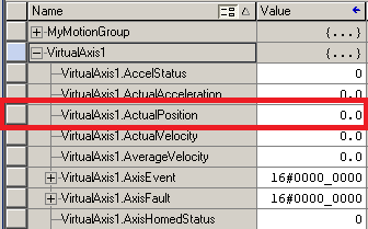
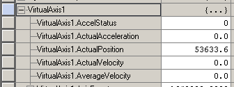
In the Controller Tag database, you will notice that tags have been created for our virtual axis. Expand VirtualAxis1 by pressing the “+” next to the tag.
![]()
Find the tag for the actual position. In the first section, we will be looking at this position as we run through the motion direct commands to ensure our axis is responding.
In the Controller Organizer window (at the left), right click on VirtualAxis1, and we will open the “Motion Direct Commands”.
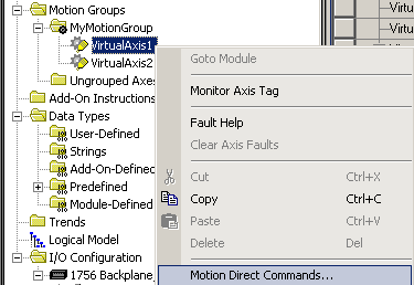
You will see the command list appear for our motion direct commands. Normally, if this were an actual axis, you would want to clear any faults or shutdown conditions with the MASR (Motion Axis Shutdown Reset), and MAFR (Motion Axis Fault Reset) commands. On an actual axis, you would then issue an MSO command (Motion Servo On). Since we are working with a virtual axis, however, the MSO command will not be functional since we don’t need to turn on an actual servo drive.
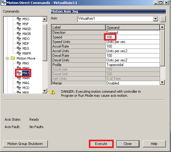
To test the motion direct commands, we will simply perform a jog. In your command list, locate the MAJ (Motion Axis Jog) command. We will set the speed at 100 units per second for this demonstration, then execute the command.
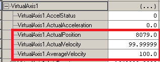
You will see the actual position is now increasing with an actual velocity of near 100 (which was our setting) and the average velocity is also 100 (or close to 100).
To stop the axis, issue an MAS (Motion Axis Stop) command.
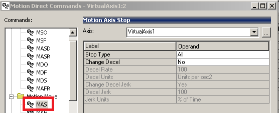
You will see that your velocity has gone to zero, and the position is no longer changing.
Other commands work very similar. You can use the help file if you need more information on how the other commands work. By using the motion direct commands on a virtual axis, you can experiment with the operation of various commands. This will help you get a good understanding of how the commands work before using them in logic.
You can execute a Motion Axis Home (MAH) command to return the axis values to the home position.
Next, you can move on to try the Motion Axis Move command!
— Ricky Bryce
In this document, we will be creating a virtual axis. The purpose of creating a virtual axis is this document will be to understand the motion direct commands, and the motion commands in logic. In a real application, we might create a virtual axis to control. The real axis could then follow the virtual axis.
An Axis can be thought of as a servo motor. Each servo motor would be a different Axis in ControlLogix, but you can also have an axis that is made up of a simple encoder that is providing a position for any part of your equipment. The creation of a virtual axis is very similar to a real axis, except we do not need a drive and servo motor to learn how the axis work!
If you have not yet done so, please read the introduction to motion control post.
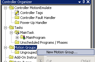
Before we add the virtual axis, we must add a motion group in Studio 5000. To do this, right click on the Motion group folder, and select “New Motion Group”.
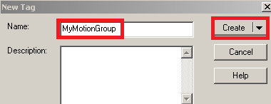
Now, we will name and create the motion group.
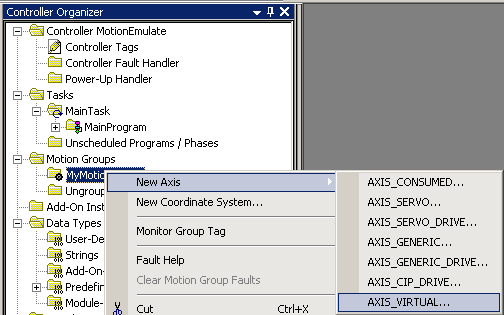
Next, we will right click “MyMotionGroup”, and create an axis. This will be “Axis Virtual”.
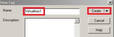
We will name the axis “VirtualAxis1” and then press “Create”.
While we are here, create “VirtualAxis2” in the same manner. Later in another document we will use both axis to show how the gearing feature works. When you are finished, your tree should appear similar to this:

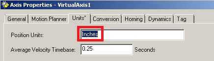
Now, right click on “VirtualAxis1” and go to “Properties”. For this example, we will go to the “Units” tab, and use “Inches”.
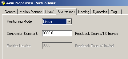
On the “Conversion” Tab, notice that we have a linear axis, and that 8000 counts on the virtual encoder will equal 1 inch of travel.
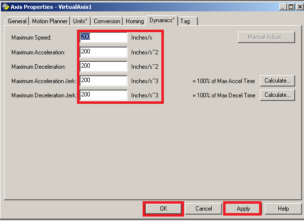
Now, we need to enter the dynamics. Go to the dynamics tab. For the purpose of other documents in this section, we will keep things simple, and enter the value of 200 for each of the parameters under dynamics. The dynamics will set the maximum speed, accel, decel, and jerk. The jerk is used in an S-curve profile. Think of accelerating from a stop sign. If you do not use jerk, then you would just press the gas pedal all the way to the floor, and you will have a constant acceleration until you are at full speed. If we use a jerk value, then we would slowly press the gas pedal to the floor. This would mean that we start off with a slow acceleration rate, and then the acceleration increases with time.
Repeat the same procedure for VirtualAxis2 using the same parameters, and you are ready to move onto the next document in this section. This document will show you how to use motion direct commands to control your axis!
— Ricky Bryce
In a ControlLogix Motion Control system, you will usually have a module in the chassis that communicates with motion drives. The drives are connected to servo motors. The purpose of a motion system is to provide precise movement. The drive is always commanding a motor to move in a certain direction. The encoder will tell the drive it’s actual position. Servo motors will typically have a high value of torque in order to hold their position once the desired position is achieved.
Examples of drives include the Kinetix 6000 (which runs on a SERCOS (fiber optic) ring), and another modern example would be a Kinetix 6500 (which runs on an Ethernet Network)
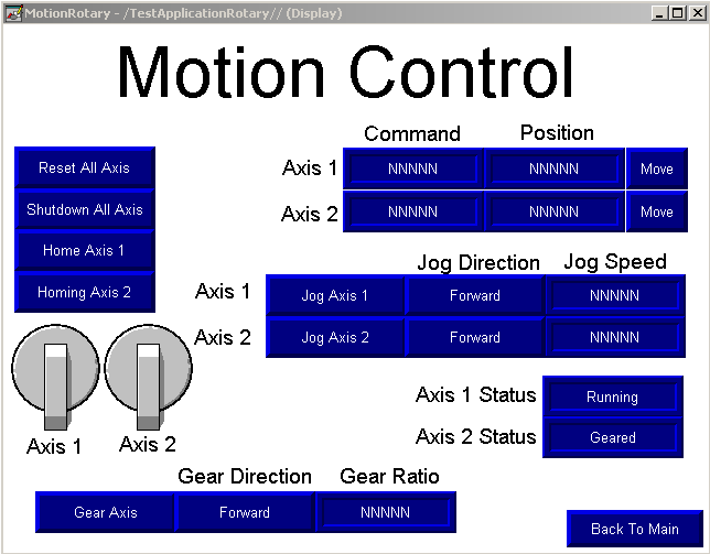
Here is an example of a screen we build in class.
Each drive in a servo system is called an “Axis”. The Axis will usually consist of a servo motor, and feedback from an encoder. Each drive could also have an “Auxiliary Axis” to which a separate encoder is attached. An example of this might be for precise timing of servo movement based on the position of another part of the machine.
An example of servo use might be in a machine that performs boxing of a product. One servo might control the horizontal axis of a pickup arm, and another servo might control the vertical axis. The horizontal axis will move a pickup arm to a specific location, and another axis might move the pickup arm up or down. Servos can also be used to close the lid on a box, and glue the box once the product is inside.
Another example of a servo would be to control the pitch of a knife when cutting a product, such as a design. One servo axis could control the location of the knife, and another servo could be used to turn the knife blade (so it’s not cutting a product sideways).
In the documentation of this category, we will learn how to set up a motion group. We will then add axis to the motion group, and issue motion direct commands. We will then use logic to control the rotation and position of the servo axis.
Move onto the next document on creating !
— Ricky Bryce