
FactoryTalk View ME (Machine Edition) is MMI (Man-Machine Interface) software. Others might refer to this as HMI (Human-Machine Interface) software. The purpose of FactoryTalk view is to allow the operator to view or input data from the processor that is controlling your equipment.
Anything added to the display screen of FactoryTalk View ME is referred to as an “Object”. The software has many objects that are pre-defined, such as push buttons, indicators, and numeric inputs and displays.
Think back to the days of when equipment had many panels of gauges, lights, and buttons. The cost of the physical devices, and the labor of wiring those devices can be very high. There was also a maintenance cost when when the devices would fail, and would need to be physically replaced.
When using FactoryTalk View, You can place most all of these devices on a computer display screen. If you need more room for the objects, simply create a new display screen. Then add buttons to allow the operator to navigate to the different displays.
FactoryTalk View also supports other features, such as alarms, information messages, security, and Macros. You can use the alarm feature to display critical events to an operator if a value. This might be a temperature that is outside of the normal operating range. Information messages are usually used to inform the operator of non-critical events. You can use this when equipment enters a different operating routine, or display other common information for the operator.
Because systems are becoming more and more dependent on computers, security has become very important. The security feature in this software allows you to create users, and give them passwords. You can then assign the users permission to access various display screens in FactoryTalk View. In addition, you can also create macros to manipulate several tags at once for common complex tasks.
Over the next few months, I will continue posting common procedures on how to develop a FactoryTalk View ME project, and explore some of the main features that are used in a FactoryTalk Application. I hope that you can use this documentation as an example to help you understand how you can develop or improve existing displays in your own plant applications.
Read the next document: How to create a new project, and set up communication!
— Ricky Bryce
When creating a FactoryTalk View project, there is some information we will first need to gather. You will need to know the model of your PanelView Plus terminal (such as Panelview 700). We also need to know the IP address of the chassis that we wish to connect to. If you have an Ethernet module in the chassis, this information will probably be scrolling across the front of the Ethernet module. If your Ethernet module is displaying “BootP”, then use the BootP server utility to assign an IP address. Another method of assigning an IP address is by using the RSWho Screen in RSLinx. Newer Ethernet Modules for ControlLogix also have on-board switches if you choose to use that method.
Next, we will Open FactoryTalk View ME Studio Machine Edition. To develop a project, we will use “Studio”. We don’t want to use “Station” yet, because that is for runtime only after our project is developed.

If you do not have a shortcut on your desktop, you can access Factory Talk View Studio by going to Start | All Programs | Rockwell Software | FactoryTalk View.
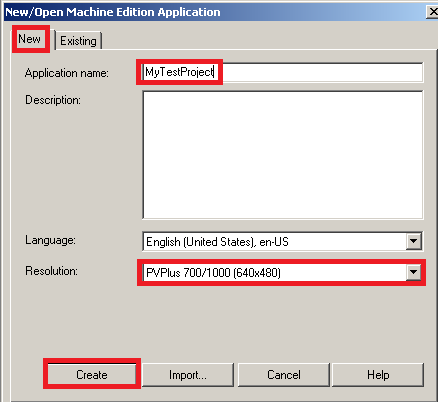
Once FactoryTalk View has been launched, let’s create a new project. Please be patient when clicking the “New” tab. This could take a few seconds to switch to the “New” tab.
Be sure to populate the name of your project, and the panelview type. Then press “Create”.
Next, we will configure communication to the processor(s) that we wish to read or write to. at the bottom of the explorer tree, we need to double click “Communciation Setup” under “RSLinx Enterprise”.

Here, we will be creating a “shortcut”. The purpose of this shortcut is to create a name that is associated with the path of your processor. Anytime we reference this shortcut, FactoryTalk View ME will know the path to your processor.
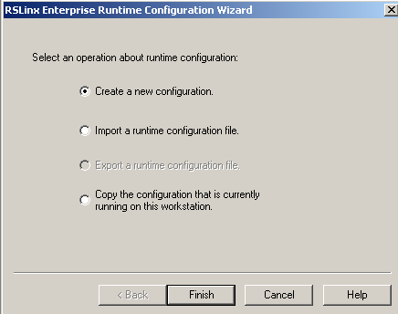
Let’s create a new configuration:
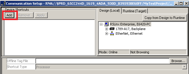
After, you press finish, we will click “Add” to add a new shortcut.
Next, name your shortcut, and specify the path of your processor.
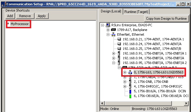
Be sure to click “Apply”

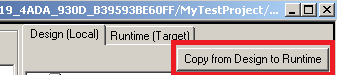
If your PanelView Terminal is running on Ethernet, and it’s on the same network as your laptop, then copy the shortcut from Design (Local) to Runtime (Target). The Design path is what you use to test your project as it’s being designed on your PC. The Runtime path is what the Panelview will use after you download your project to the Panelview Plus Terminal.
Press OK, and your communication is complete. You are ready to continue to the next document to begin developing display screens, and adding objects.
Next learn about navigating between display screens!
— Ricky Bryce
You’ve seen pictures of the old control centers with many panels that contained various gauges, push buttons, and other indicators. In modern times, most of those devices can simply be placed on display screens. The operator needs to be able to quickly locate the control that he is looking for. To accomplish this, you will usually organize your projects into different display screens. In this document, we will discuss FactoryTalk View Navigation.
Once we add other display screens to the project, you will need to add navigation buttons. This allows the operator to move between different screens in your project. Once the operator gets to a display screen, don’t forget to allow the operator to navigate back to the main screen.
If you expand “Graphics” in the Explorer tree, and you will see that we have a main screen. By default, this is the screen that will come up first when the project is first started. You can change this screen under “Startup” in the explorer tree.

Next, let’s right-click “Displays” to add a new display screen. We’ll add a text object to this screen called “Pump Control”. To access the Text object, click on Objects | Drawing | Text.

We will add the text to the top of your new display screen as shown. You can change the size, color, fonts, etc… on the same screen that you are typing the text. If you wish to change this later, you can access the properties screen by double clicking the object. Another way to access the properties screen is to right click the object and choose “Properties”.

When the operator is on this screen, we need to have a way for the operator to navigate to the main screen. Choose Objects | Display Navigation | Goto. Draw the “Goto” object on your display screen.

On the “General Tab”, click the elipsis next to the Display text box. Configure this object as shown so when the operator presses the button, he will be taken to the main screen.

Even though we told the object to go to the main screen once the button is pressed, we have not told the operator the purpose of the button. We will do this under the “Label” tab.

Your object should appear as shown:

Now, we will close the display with the X in the upper right hand corner, and save the screen as “Pump Control”

We have now saved the Pump Control Screen. Follow the same procedure to add a goto button to the Main screen. Set the display to “Pump Control” (on the general tab). The label for the operator will read “Go to Pump Control”. Don’t forget to add text to the top of the main screen as shown. This tells the operator which screen he is currently on.

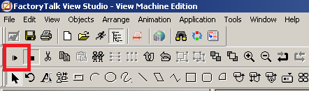
To test your navigation, press the “Test Application” button in the standard toolbar.

Another way to add the navigation buttons is to copy them from one screen and past them on another, making basic changes to the properties of the object. This helps to maintain a consistent size across all of your screens.
If you have a Panelview Terminal without a touch screen (keypad only), you will want to relate the objects to function keys. If you need to establish this relationship, please include the function key in your object label for the operator. This tells the operator which function key to press to navigate between screens. To relate the objects to function keys, right click any blank area on the display, and choose “Key Assignments.

Next, learn how to set up a FactoryTalk View Push Button object!
— Ricky Bryce
The FactoryTalk View Push Button Object is very simple to add to your project. Using push buttons on a FactoryTalk View display saves time and money. Think about the cost of a physical button on a panel. Each button alone can cost over $50. Then you have the time spent to knock out a hole in the panel, wiring, and the cost of the input module on the processor.
Most objects on a FactoryTalk View display screen take less than a minute to set up. The push buttons can be either maintained, or momentary. Maintained pushbuttons will write the value of 1 to a memory location in the processor. When the button is released, the value will remain at 1 until the operator presses the button again. Momentary push buttons will write the value of 1 only while the operator is pressing the button. When the button is released, a 0 is written to the memory location the object is pointing to.
Consider this line of logic:
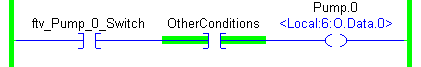
Our goal will be to create a maintained push button. This pushbutton will write the value of 1 to ftv_Pump_0_Switch. As long as other conditions are made (such as a lube pump), then we will start Pump.0.
In our situation, we have created a display called “Pump Control” that we will add the object to. We will assume that you already have a shortcut created in RSLinx Enterprise.
In FactoryTalk View, select Objects | Push Button | Maintained.

Next, draw your object onto the display screen, and the properties box will appear. On the “States” Tab, for “State 0”, we will create the text “Request Pump 0 Start”. This will tell the operatore that he needs to press this button to start pump 0.

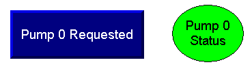
Let’s do the same thing for State 1. Remember this is a maintained pushbutton, so the text should reflect that the value of 1 is being written to the processor. Our text will read “Pump 0 Requested”.

Now we have to relate this object to a tag in the processor. In RSLinx Enterprise, I’ve set up a shortcut called “MyProcessor”. Whenever this shortcut is referenced, FactoryTalk View will know the path to the processor. Remember the tag we are writing to is “ftv_Pump_0_Switch”. We will set this up on the Connections Tab.
On the Connections Tab, press the Elipsis button. This will let us browse for the tag that we wish to write to.

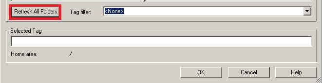
First, click “Refresh All Folders” to ensure you are seeing the latest tags that you’ve added to the processor.
Next, we will browse for the tag that we wish to write to when the operator presses the button.

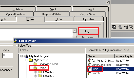
Remember that your basic (atomic) data types are in the ONLINE folder. You must click the ONLINE folder itself to be able to see these tags. Once “ftv_Pump_0_Switch” is selected, press “Apply” and “OK”.
Your Value box should look like this:

By default, the state shown on the button will be the same as the value tag (look at the arrows). If the state needs to be reflected by a different tag, when we would populate the “Indicator” field. Remember that our pump will not actually run until the “OtherConditions” tag is true. If we wanted the button text to reflect if the pump was actually running or not, we could set the Indicator tag to Pump.0 (see the logic above). In this case, though, our button text is just reflecting if a start has been requested or not, so we will leave the Indicator field blank. In another post, I will show you how to add an elipse object to indicate the actual state of the pump.
Now that everything is set up properly, press “Apply” then “OK”. Let’s test our screen. We don’t need to do a full application test to see if this object will work. We can just click the “Test Display” icon.
Now press the button we just added to test the connection.

You will then see that your logic is true.

Next, learn how to configure the color animation of an ellipse object!
— Ricky Bryce
In this document we will walk through the procedure of setting up the FactoryTalk View Ellipse Animation to simulate an indicator light. When a pump is running, the ellipse object will be green, and when the pump is shut off, the ellipse object will be red.
Consider the following logic:
The color of our ellipse object will reflect the state of the tag Pump.0. We will assume that you already have communication established in RSLinx Enterprise.
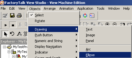
First, we will add the ellipse object to our FactoryTalk View display. This will be under Objects | Drawing | Ellipse.
Draw the object on your display:
You can cancel the properties screen that appears. Then right click anywhere on the screen to release the object, so we don’t continue drawing more objects every time we click on the screen.
We will also add a text object on top of the Ellipse, so the operator knows what the Ellipse is indicating. You can get to the text object through Objects | Drawing | Text.

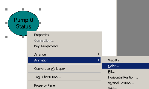
Next, we will right click on the Ellipse object. Here, I will right click the bottom edge of the ellipse object to make sure I’m on the Ellipse and not on the text object. Then we will choose Animation | Color.
Press the button to browse for tags, and in the online folder, we will select “Pump”. Then press OK.
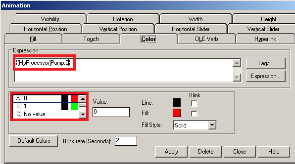
Pump is an alias to the entire output card, so we need to choose which pump we need the ellipse object to monitor. Let’s add a .0 (dot zero) after the pump in our expression box. While we are still on this screen, verify the states are set to the correct colors.
Press “Apply” then “close”. Next we will test our display screen to ensure our ellipse object is working properly.
As long as the “OtherConditions” bit is set, the ellipse will be green when the pump is on, and red when the pump is off.
Many other animations such as visibility, position, rotation work in a very similar way. Just choose the animation that you want to configure on an object, point the animation to a particular tag in the processor, and configure a few parameters to adjust the animation to your specifications!
Continue to the next section — Numeric Displays.
— Ricky Bryce
In this document, we will discuss how to add and configure the FactoryTalk View Numeric Display. The purpose of the Numeric Display object is to display decimal numbers that are stored in the processor’s memory. This could be the speed of a drive, temperatures, or pressures.
We discussed the push button object in another section, which points to a tag with a BOOL data type. The numeric display however, will point to a tag that has a numeric datatype such as DINT or INT.
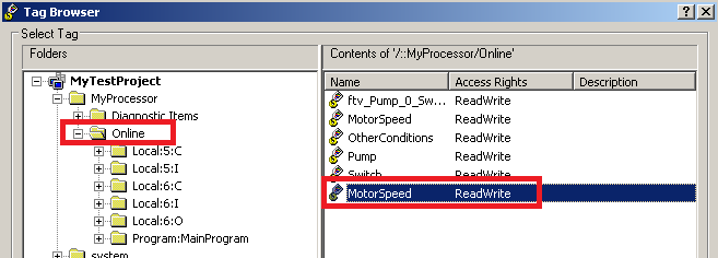
In this example, we have a tag called “MotorSpeed” in our Controller tag database. This tag currently has the value of 3600. We will display this value for the operator to read.
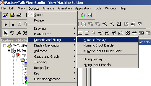
First, lets select the numeric display by clicking Objects | Numeric and String | Numeric Display.
Then we will draw the Numeric Display object onto our display screen. You will notice that after you draw the object on the screen, the properties window appears.
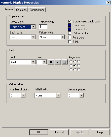
Be sure that the number of digits that you are displaying is large enough to hold the maximum number of digits you would expect in the tag. For example: If we expect the maximum value to be 10000, our number of digits will need to be 5.
Next, we will go to the connection tab. Here we will select the Ellipsis (…) to choose the tag we wish to display.
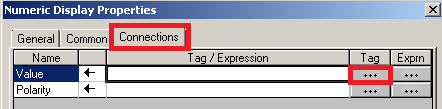
You may want to refresh all of the folders to ensure that all the tags are being displayed for possible selection.
Here, we will select the “MotorSpeed” tag in the “Online” Folder.
Hit OK, then Apply, and OK on the next screen. On the FactoryTalk display, you can right click the screen to drop your object. This will ensure that you don’t continuously draw Numeric Displays every time you click on the screen!
Let’s add a text label above the Numeric Display. This will tell the operator the purpose of the number he’s looking at.

Finally, let’s test the display screen to ensure we are viewing the numeric data in the processor.
We can see that the display is working, and showing the correct numeric value!

Next topic: Numeric Input Cursor Enable
— Ricky Bryce
In this section, we will discuss the FactoryTalk View Numeric Entry (cursor point) object. The purpose of the numeric input is to allow the operator to enter values into the processor. This could be the speed set-point of a drive, a temperature set-point, or the preset of a timer or counter.
The Numeric input will write to a numeric data type in the processor’s memory such as a DINT or an INT.
In this example, we will add a numeric input cursor point object to our display screen that allows the operator to change a speed set-point. Let’s look at the tag in our controller tag database.
![]()
Right now, this tag has the value of 0. If this works properly, the operator should be able to change this value from our display screen.
First, let’s add the Numerc Input Cursor Point object onto our screen. To do this, click Objects | Numeric and String | Numeric Input Cursor Point.

Now, we’ll draw this object onto our screen, and the properties window will appear.
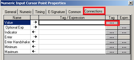
Go to the connections tab, and press the Ellipsis (…) to choose the tag that we will be writing to in the value field.
Be sure to refresh all folders before selecting the tag to ensure the latest tags are appearing for selection.
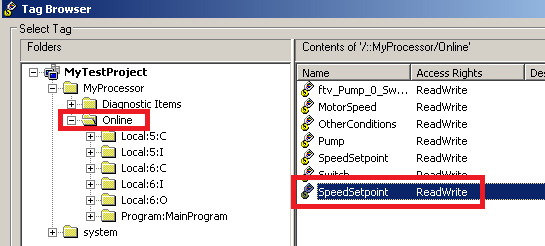
In the Online folder, select the SpeedSetpoint Tag.
Press OK.
There are a lot of other options for the Numeric Input cursor point object. To understand what the other options are used for, you can click “Help”. In this example, we will just keep things simple, so press “Apply”, then “OK”.
Be sure to add a text object to label the purpose of this numeric input object.

Now, test the display.
When you click the object, a keypad should appear. Enter a new setpoint, then press the enter key.

Now, let’s verify our work by going to the Controller tag database in Studio 5000.
![]()
We can see the value is updating perfectly!!!!
— Ricky Bryce
FactoryTalk View Security allows you to secure displays screens or objects with a password. In this document, we will learn how to set up the users, and secure a display screen. You can also configure groups of users to better organize them, but we will keep things simple in this document.
We will:
For example: Joe is assigned to class A, B, and C. Jane is assigned security class A and B only. If we have a pump control display assigned to security class B, then both Joe and Jane can access the display. If we have a motor control display assigned to security class C, then only Joe could access this display.
In the explorer tree, scroll to the bottom to find the System folder. Expand the system folder, and you will find “Users and Groups”. Expand “Users and Groups”, and you will see the “Users” folder. Right-click the “Users” folder, and select New | User.

Next, populate the required (and desired) fields to set up the user.

Now hit OK. Your user is added.
Next we will assign the user to security classes under “Runtime Security”

Before we move on, let’s remove all security classes except for class “A” from the default user. The default user is considered the active user when no other user is logged in. We will use security class A for the Main Screen later on. This will allow anyone to still see the main screen when no one is logged in. The main screen is where we will later place the login and logout buttons.

Now, we’ll click the “Add” button. Be sure to select “Show Users Only” (for what we are doing here). Then select the name of the user you wish to configure. Now press OK.

Now, be sure your user is selected. In this example, we will select the user “Joe”. Joe will have access to security class “A”, “B”, and “C”. Be sure to press the Accept button when you are finished. If you don’t press accept, the security classes for the user will not be updated!!!

After you press “Accept”, you will see the security classes update for the user. When you are finished, press the “Close” button, and save your changes.
![]()
In this project, we have 3 total screens. Main Screen, Pump Control, and Motor Control. We want Joe to have access to any of these screens. If no user is logged in, though, the default user should only have access to the main screen. We will assume that you also have navigation configured between the screens.
Open the Main Screen, and add a Login Button and a Logout Button. The Login and Logout buttons can be found under Objects | Advanced.

When finished, your main screen should appear similar to this:

Next we need to configure the Pump Control and Motor Control screens to be in a security class. We will make the “Pump Control” screen have a security class of “B”. The “Motor Control” screen will have a security class of “C”.
Open the “Pump Control” Display. Right-click the Pump Control display and go to “Display Settings”. You can then assign the security class of “B”.

Using the same procedure, set the Motor Control screen to a security class of “C”.
Now, as a review, add another user called “Jane” that has access to security class A and B only.
Test run your project, and attempt to access a secured display screen. Notice that you will not be able to access the display until you log in. Test your work. When you are logged in as Joe, you can access any screen. When logged in as Jane, you cannot access the “Motor Control” screen, but you can access the “Pump Control” Screen.
— Ricky Bryce
Once a project is created and tested, the next step is to download the project to the Panelview Plus terminal unless you wish to run the application on your desktop. If you are unfamiliar with how to start a project, read up on how to Create the FactoryTalk Project.
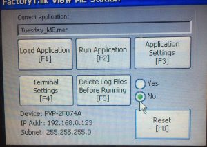
Before we download, you must first identify the revision of the Panelview Plus. We can get this revision from the configuration screen. If you do not have a “Shutdown” or “Configuration Mode” button, press the square in the lower left corner as the terminal boots up.
In the Configuration screen, go to Terminal Settings | System Information | About FractoryTalk View ME Station. Be sure to write down the Revision.
We will also need the IP address. To get the IP address, go to Terminal Settings, | Networks and Communications | Network Connections | Adapter Adapters, and press F2 to get (or set) the IP address. In our case, the IP address is 192.168.0.123
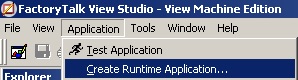
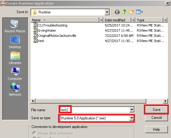
Go to Application | Create Runtime Application.
Next, we must name the runtime. We will leave this at default, and let it assume the name of our studio application. It’s very important to select the correct revision!!! Then click “Save”
You will see a progress bar as your runtime is being created. Be patient with this.
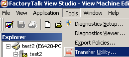
After the runtime is created, we will transfer the application to the terminal. Select Tools | Transfer Utility.
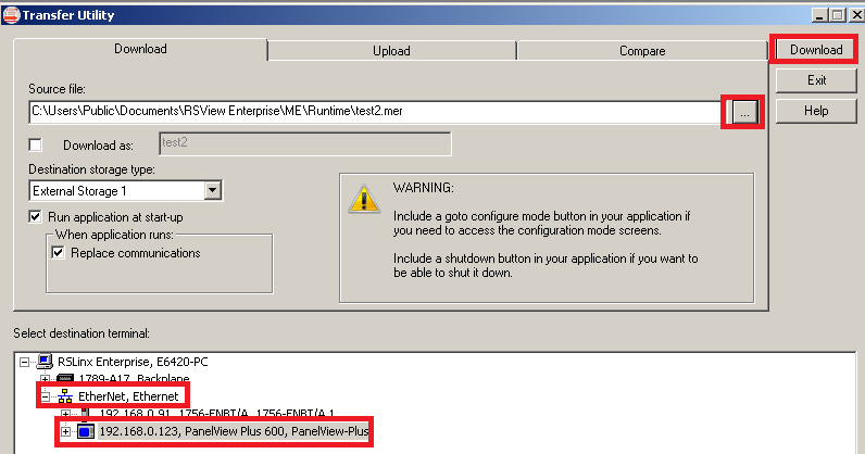
Be sure to press the Ellipsis (…) and select the runtime that you just created. Browse for your panelview terminal, then click “Download”
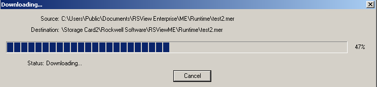
You will now see a progress bar.
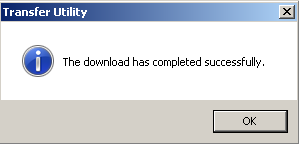
When you are finished, you will receive a message that your transfer has completed successfully.
When you are finished, please be very patient. It takes a while for the Panelview terminal to boot up after a download. If you get an error that states the firmware revision is incorrect, double check the firmware of the terminal, and create a new runtime.
— Ricky Bryce
FactoryTalk View alarms are used to inform the operator that a specific condition has occurred. Examples include a high oil temperature, low water pressure, or even a jam on a conveyor system.
We will configure FactoryTalk View alarms lto look for a “Trigger”. When the trigger condition is met, we will program an alarm message to display for the operator.
In this document, we will configure a simple alarm. If a bit goes true, we will display an alarm message for the operator.
Before we configure alarms, be sure you have a FactoryTalk View project created, and communications are set up in RSLinx Enterprise. If you have not done that yet, click here to read the document on creating a new project and setting up communication.
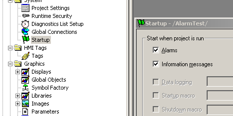
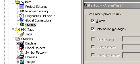
Go to Startup in FactoryTalk View to ensure the alarm features is enabled to run in the background.
Under Alarm Setup, you will start with the “Triggers” tab.
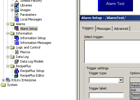
The options for the trigger type are Value, Bit, or LSBit (Least Significant Bit). The trigger type of “Value” can be used on a single bit or an entire word. By using “Value”, you are going to monitor a numeric value of a tag, and based on the numeric value, a message will be generated (from the messages tab in the next step). If you choose “Bit”, the tag you monitor must be an entire word, such as a DINT (Double Integer). The alarms will then look for a bit to go true within the word to trigger a message. By using LSBit, the Least significant bit to go high within a word will trigger a message.
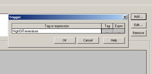
Click “Add” to add a trigger, then browse to the tag that you wish to monitor. (Then press OK).
On the “Messages” tab, select the trigger that we created. Since this is a single bit, we will look for a value of 1. Also, be sure to enter the message the operator will see.
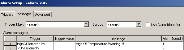
Our example here is very simple, because the alarm feature is configured to look at a single bit. If you are monitoring an entire word, and the trigger type is “Bit”, then you must enter the bit number for the trigger value. Be warned, however, that the trigger values are off by one. For example, if bit 0 goes high, the message with a trigger value of 1 will appear. If bit 1 goes high within the word, then the message with a trigger value of 2 will appear, and so on.
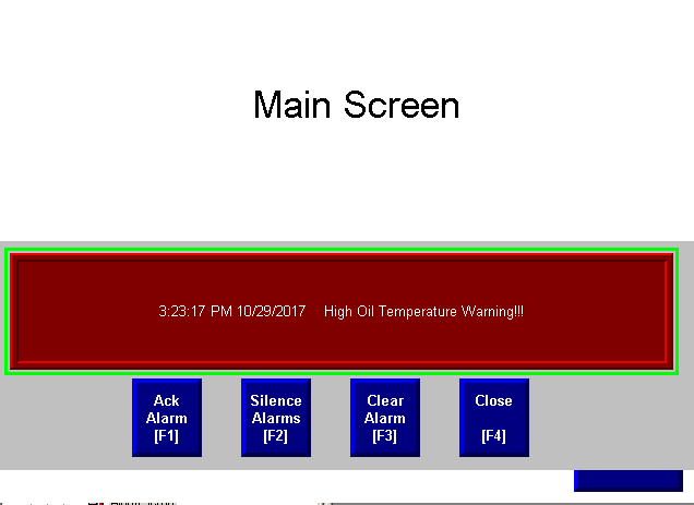
Now, to test our alarm, we must do a full test run, because alarms are a background feature of FactoryTalk View.

When our alarm condition is met, the alarm will appear for the operator.
For more information on alarms and other features, go to Help | Online Books | Users Guide!
— Ricky Bryce
Information messages are useful for informing the operator of various events that occur on the equipment. This is not an alarm, because the Alarm feature is used for that. An example of an information message include the fact that the machine has entered a new state. Another example would be that the battery is low on the processor and needs to be replaced.
If you have not done so yet, please see the document on how to create a new FactoryTalk View project.
Information messages run as a background process. To use information messages, be sure this feature is turned on under “Startup”.
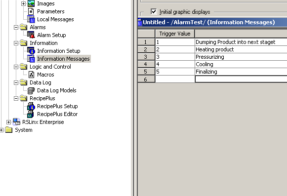
Next, double click on “Information Messages”. Here you will configure a list of messages. In the program in the PLC, the processor will place a value into a tag. The value of this tag will determine which message to display. I’ll just set up the messages for now, and later, I will specify which tag the processor is going to look at.
Next, close the information message list, and save the file as “MyMessageList”.

Next, the information message list has to be connected to a tag. As a result, the value of the tag that we connect the list to will determine which message appears.
In order to connect this, go to “Information Setup”. Furthermore , you will choose the information file that you created earlier. Be sure to browse for the tag in the processor that you wish to monitor.
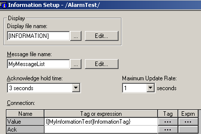
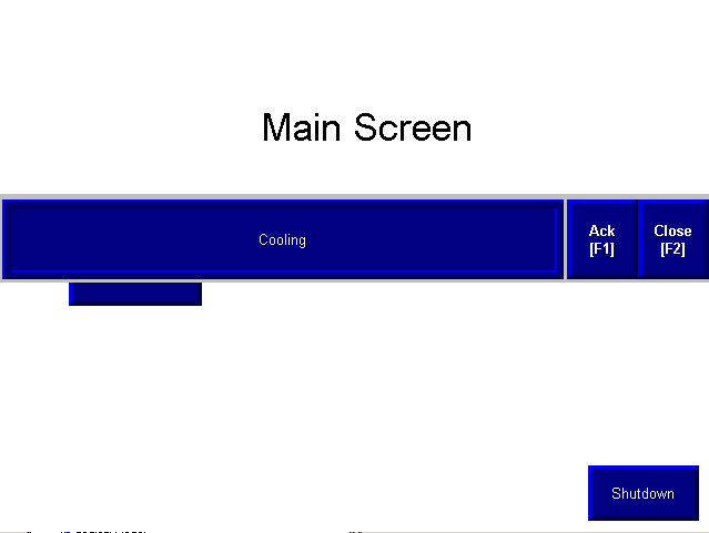
Finally, you will perform a full test run. Based on the value the processor places into “InformationTag”, the appropriate message will be displayed for the operator. Perform a full “Test Run”.
Futhermore, the processor will place a value into “InformationTag”. The value the processor places into this tag will control which Information message will be displayed.
Here, I’ve placed the value of 4 into “InformationTag” in the processor. Of course, you will see the message, “Cooling”. The alarm list was configured to display the text “Cooling” if “InformationTag” has a value of 4.
FactoryTalk View Parameters are used to identify placeholders on a screen. For example: If we have 9 tanks in a tank farm, you can just create one tank screen. The objects on the tank screen will use place holders instead of tags. When the operator presses a button for a particular tank, a parameter file is loaded. The parameter file assigns tags to the placeholders on the display screen. Each tank would use a different set of tags.
This means you will have 9 navigation buttons that navigate to the same screen. Each navigation button will reference a different parameter file.
Now, we’ll look at an example of some simple code. This code will have 3 timers. When the operator requests a light to be energized, the timer will start. When the timer is finished, the light will energize.

In FactoryTalk View, create a new display screen called “Lights”. We will add the objects as follows:
First, add a Maintained pushbutton object. The purpose of this button will be to request that a light be energized. Instead of a tag, we will just use a place holder (#1 as shown).

Let’s also add an Ellipse object. In the ellipse, you will choose the color animation. Set this tag to be “#2”.
Next, add a numeric display. This will eventually display the accumulated value of the time. The placeholder will be “#3” (in place of the tag)
Finally, add a Numeric Entry Cursor Point object. The place holder will be “#4” instead of using a tag. Your screen should appear similar to this: Don’t forget your navigation button to get back to the previous screen.

Exit the display screen, and save your display as “Lights”.
Next, go to “Parameters”. We will set up the first parameter file as follows:

Exit the parameter file, and save the file as “LightAParameters”.
Create another parameter file with the following information:

Let’s create the last parameter file for controlling Light C as shown:

When finished, you should have 3 parameter files as shown:

Now, let’s go back to our main screen. We will create 3 navigation buttons. The first navigation will pass the parameter files that defines the tags for the placeholders for light A. The second button will pass a different set of tags to use with the objects for light B. Lastly, the third button will define the tags to be used for light C.
Add your first navigation button by going to Objects | Display Navigation | Goto.
Be sure to select “Lights” as your display. We will use the parameter file “LightAParameters”. While you are here, please also go to the “Label” tab, to inform the operator that this button is for light “A”.

Add Two more navigation buttons. All of these navigation buttons will go to the same display, which is “Lights”, but the second button will load the “LightBParameters” file. The third button will load the “LightCParameters” file. When finished your screen should appear similar to the one shown.

Now do a full test run of your project. When you click the button for “Light A”, you are controlling Light A in logic. Return to the main screen, and use the Light B button. You will see that it’s now light B that you are controlling. Try the same thing with Light C.
Parameters save memory, and time. If you decide to make a change later to the screen, you only need to maintain one display screen for all similar objects.
— Ricky Bryce
For security reasons, there might be some objects on a display screen that you would like to hide until a particular user is logged in. This could be a temperature preset, or a timer preset that you don’t want a standard operator to access. We will configure our security so we are hiding objects when logged out.
We will walk through four steps to make this happen:
Please read the document on FactoryTalk View Security before you continue.
We will create an internal memory tag within FactoryTalk View. You can also create this tag within the ControlLogix processor if the program depends on a user being logged in.
Under HMI Tags, open the tag database. Configure the tag as follows:
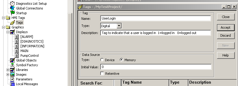
Be sure to accept your new tag.
We need to create two macros. The first macro will be used to set this tag to the value of 1. The second macro will reset this tag to the value of 0.
Right click the macros in the explorer tree to create the first macro as follows. When the macro runs, our tag will be set to 1.

Close the macro, and save this as “LoggedIn”
Create a new macro as follows: This macro will reset the our bit back to 0.

Close the macro, and save this one as “LoggedOut”.
Go to “Runtime Security” in the explorer tree. Click on the user who will be logged in when the macro becomes visible. Configure the Login and Logout macros as follows: Be sure to press “Accept”, or your changes will be lost!!!

The last thing we need to do is to configure the object so it is invisible until the user is logged in. Right-click the object you wish to hide, and go to Animation | Visibility.

Configure the visibility animation as follows:

Finally, be sure to select the tag that we are setting and resetting with the macros. Now, when the user is logged in, the UserLogin tag is 1. This makes the object visible. When the user is logged out, the object becomes invisible.
Test run your project!
— Ricky Bryce
Before we download to the Panelview Plus terminal over Ethernet, we need to get into the Panelview Plus Configuration screen. This will help you to determine the IP address if it is already set up. We also need to determine the firmware revision of the Panelivew. You will need this before creating your runtime in FactoryTalk View.
If your Panelview Plus has an “Exit” or “Configuration” button, you can use that. By default, you will find a “Shutdown” button on the main screen. The programmer will sometimes remove this, or place it on a secure screen for security reasons. If your application does not have one of these buttons, reboot the terminal. When you reboot, you will see a square appear in the lower left screen of the Panelview terminal. Hold this square to enter configuration mode.
The IP address is displayed in the lower left portion of the configuration screen if it is already configured.
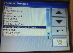
If you need to configure the IP address, go to “Terminal Settings” on this configuration screen.
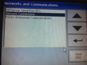
Second, choose “Networks and Communications”.
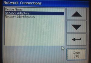
Now we will choose Network Connections.
Next, go to “Network Adaptors”.
Then, be sure the Built-In Ethernet Controller is selected, and choose “IP Address”.
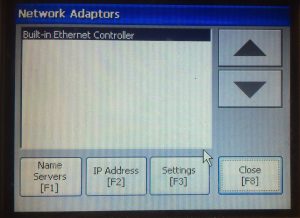
Finally, you can set up the Ip address.
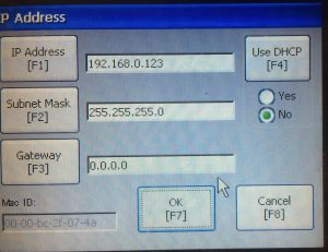
Be sure to exit back to the main configuration screen after setting the IP address (and Subnet Mask), then reset the terminal!
Before downloading to the Panelview Plus terminal, we will need to know the revision of the terminal. When you create the runtime project from FactoryTalk View ME, you will need to select the revision of the terminal you are downloading to.
From the Configuration menu, choose, “Terminal Settings”.
Then, go to “System Information”.
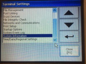
Next, we will choose “About FactoryTalk View ME”.
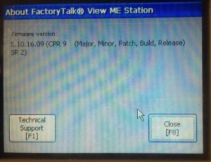
Now your version will be listed on your screen. To get started with a new project in FactoryTalk View ME, you can start here with this link!
For general information on FactoryTalk View ME, visit the FactoryTalk Category page!
— Ricky Bryce