
Introduction to Common Logic Gates
We use common logic gates to display the flow of a process. These gates include AND, OR, NOT, NAND, NOR, XOR, and XNOR. These logic gates convert a process into plain English in a way that anyone can understand how they work. By the same token, you can convert plain English into logic.
Straightaway, let’s go through each of these logic gates to show their meaning and functionality. To demonstrate, in all of these examples, we’ll have two inputs and one output.
I’ve used RSLogix / Studio 5000 for the ladder logic examples. In addition, I’m using Logic Gate Simulator to display the common logic gates.
Logic AND Gate
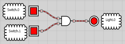
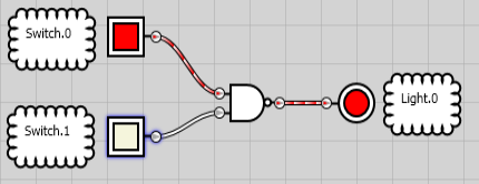
At this point, we’ll take a look at the AND gate to see how it works. Basically, ALL of your inputs need to be on. Keep in mind the following statement: If Switch.0 AND Switch.1 THEN Light.0
In this case, both Switch.0 AND Switch.1 must be on to energize Light.0 Here is an example in ladder logic of how we would do this.
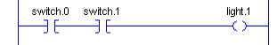
Simply energizing switch.0 will not energize the light. Likewise, energizing switch.1 ONLY will not energize the light. Switch.0 AND Switch.1 must be energized. A typical example might be for a hydraulic valve. We might say that IF the operator calls for the valve to open, AND the hydraulic pump is running, then open the valve.
Let’s also look at the formal symbol for the AND statement:
Logic OR Gate
Another gate is the OR gate. In this case, only one input needs to be on to energize the output. Keep in mind the following statement: If Switch.0 OR Switch.1 THEN Light.1
In this case, only ONE input needs to be on for the output to energize. Below is an example in ladder logic:
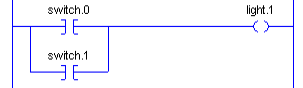
Energizing either one of the inputs will energize the output. For example: The output might be turned on from the local station, OR from the MMI (Man-Machine Interface). Let’s look at the formal symbol for an OR statement.
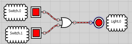
Note: The OR symbol does NOT have a circle on the right side of it. That is just a connection point in the software.
Common Logic Gates — Logic NOT Gate
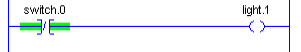
The NOT gate simply inverts the signal. If it receives a 1, it will send out a 0. Likewise, if it receives a 0, the output will be a 1. Consider the following statement: IF NOT Switch.0 THEN Light.1.
An example of a NOT might be for an alarm. If an alarm condition goes true, then you do NOT want the output to energize.
Let’s take a look at ladder logic for a NOT statement.
In addition, we’ll look at the formal diagram:
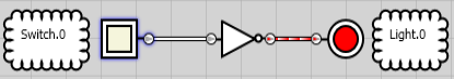
Notice the circle after the NOT statement. This means the output is inverted.
Logic NAND Gate
This gate works very similar to the AND gate with one exception. The output is inverted. In other words, if both Switch.0 AND Switch.1 are energized, the output will be off. Otherwise, the output is on.
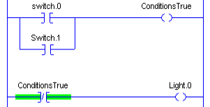
We might use this gate for fail-safe reasons where the logic needs to be reversed. First, let’s look at an example in ladder logic.
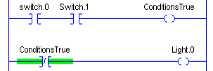
Obviously, when we energize Switch.0 AND Switch.1, “ConditionsTrue” becomes a 1. Once this happens, Light.0 goes to 0.. Otherwise, we send a value of 0 to Light.0
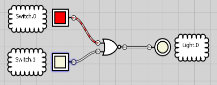
Again, let’s look at the formal symbol. Also notice the circle at the end of the AND symbol. This circle means the value reverses, and is therefore a NAND Statement.
If both inputs are ON, the output is OFF.
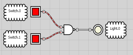
Likewise, if one input shuts off (or both), the output energizes.
Logic NOR Gate
Again, the only difference between the OR and the NOR is that the output reverses. This means that if EITHER switch energizes, the output will be false. A typical example for this would be normally closed switches.
Here is a diagram in ladder logic of how this works.
As you can see, either one of the switches will energize the “ConditionsTrue” bit. In turn, this shuts off our light.
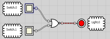
Once again, let’s look at the formal diagram for the NOR gate. Notice the circle attached to the right side of the OR gate. This indicates the output reverses.
If at least one input is on, the output is off. Once both switches are off, the output will then erergize.
Common Logic Gates — XOR Gate (Exclusive OR)
The main difference between the OR and the XOR (Exclusive OR) is that only one condition must be true for the output to energize. In this case, if both outputs are ON or OFF, the output will not energize. Exclusive means one or the other, but NOT both. If we hold one input of the XOR high, the XOR will act as an inverter (or NOT).
Let’s take a look at ladder logic that will simulate the XOR statement:
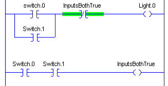
Notice that ONE condition OR the other will energize our light. However, if BOTH conditions are true, the light will not energize.
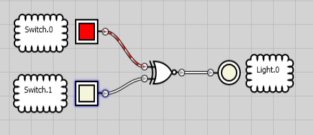
Once again, let’s look at the formal symbol for the XOR Statement.
As you can see one condition will energize the output. Again, there is not a circle at the end of the XOR symbol… That is simply a connection point in the software.
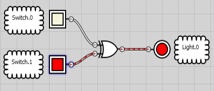
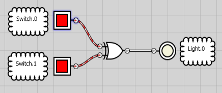
If both conditions are true, though, the output does not energize.
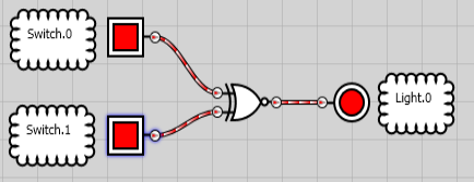
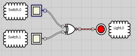
Logic XNOR Gate (Exclusive NOR)
Finally, we’ll talk about the XNOR (Exclusive NOR Statement). Obviously, this one is a little bit confusing. However, it works exactly as the XOR statement does with one exception. It inverts the output.
It’s the same as feeding the output from the XOR through a NOT. Let’s look at an example in ladder logic.
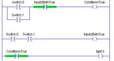
If one input is high, but not both, the output shuts off. Otherwise, the output turns on. Let’s take a closer look at the formal diagram for the XNOR:
If one input goes true, the output is OFF.
If BOTH Inputs go true (or no inputs), the output is ON:
Summary — Common Logic Gates
In summary, to get an output —
- AND — Both Inputs must be ON
- OR — One or both inputs must be ON
- NOT — Input must be OFF
- NAND — At least one input is OFF
- NOR — Both inputs OFF
- XOR — One input or the other (but not both) must be ON
- XNOR — At least one input must be OFF (but not both)
For more information, visit the Arduino Beginner, or ControlLogix category Pages!
— Ricky Bryce