
Introduction to the Altair BASIC Stopwatch
In this section, we’ll write an Altair BASIC Stopwatch. Basically, we’ll use the first sensor input (switch 8) to start and stop the watch. When we turn on switch 8, the stopwatch will start. After that, if we shut off switch #8, the clock will start a new line. This leaves the old value on your display. When you start the stop watch again, your seconds will display on the next line. Although I’m writing this in Altair BASIC, it should work with just about any old version of BASIC.
I use this program to clock PID cycles, and it’s close enough for that. If you desire more accuracy, you can play around with the delay loop, and add some null code.
Booting to Altair BASIC
I’m writing this code on the AltairDuino. You can purchase the kit, or build one yourself. For the most part, this is an Arduino DUE with some drivers to drive all the LED’s, and an SD Card. You simply wire the SD Card adapter to the SPI header. This SD Card has the drive images on it that we will use.
Without further delay, let’s boot to Altair BASIC. Be sure to connect to your AltairDuino through a terminal emulator such as PUTTY or TeraTerm. Turn on switches 23, 12, and 0. Press AUX 2 down. This will mount your drive.
Next, we need to boot to the Altair BASIC disk. Simply turn on switches 3, 2, and 1 (and only those switches!). Then press AUX 1 down to boot. Press ENTER on the memory size. For Line Printer, I use capitol C. Highest disk number is 0. We’ll put 4 for the number of files we can have open. Additionally, enter the day, month, and year.
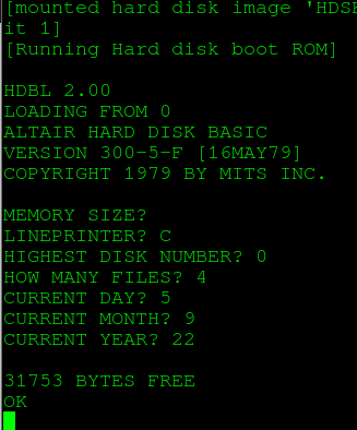
Now, type MOUNT to mound the disk to BASIC. Type FILES, and you will see the files on your hard drive.
Write the Code for the Altair BASIC Stopwatch
At this point, type NEW to be sure we don’t have any BASIC code in memory. We are ready to start writing the program.
Here is our code:
10 LET X = 1
15 I = INP(255)
17 IF I <> 1 THEN 15
20 LET Y = 56
30 LET I = INP(255)
32 IF I = 0 THEN PRINT " " : GOTO 10
35 LET Y = Y - 1
40 IF Y <> 0 THEN 30
45 LET N = 0 : LET N = 0 : LET N = 0
46 LET N = 0
50 PRINT CHR$(8);: PRINT CHR$(8);: PRINT CHR$(8);
60 IF X > 10 THEN PRINT CHR$(8);
70 IF X > 100 THEN PRINT CHR$(8);
80 IF X > 1000 THEN PRINT CHR$(8);
85 IF X > 10000 THEN PRINT CHR$(8);
90 PRINT X;
100 LET X = X + 1
110 GOTO 20
In line 10, we’ll initialize X to 1. In line 15 and 17, we are checking for the first sensor switch to go high. As long as switch 8 is off, we are stuck in this loop.
Once you set switch 8 to ON, the program drops down to line 20. Here we set Y to 56. This is really just a calibration value. The program will hold in this loop between lines 30 and 40 for one second. While in this loop, we check for the sensor switch again. If the user shuts off switch 8, the program will print a blank line, then start all over. The loop begins at Y=56. The Y variable continues to decrement every time the loop executes. In line #40, if Y reaches 0, then we drop to line 45.
Lines 45 and 46 simply have no purpose than to delay the processor. The more “LET N = 0” statements, the slower the program runs. Think as line 20 as a “course adjust” for the timer, and lines 45 and 46 are a “fine adjust”. Depending on the scan time isn’t exactly the best way to do this, but it does give us the ability to make some adjustment if we need to. Line 50 to 85 simply add more backspaces when we have more numbers to print. For example: 99 requires more backspaces than 9 to erase the previous value from your display.
Finally in line #90, we print the value of X, Increment X, and then go back to line 20 to start the delay loop over again for 1 second.
Test your Program
To test the program, type RUN. After that, turn on switch 8. You will see the seconds increment in real time. Once you shut off switch 8, the timer stops. When you turn on switch 8 again, the timer will start over again on a new line. This allows us to time multiple events.
Work on the timer, and improve it. Try to make it count down if you like. It’s a great way to learn BASIC, so you can start writing your own projects.
For more information, visit the vintage computer category page!
— Ricky Bryce