
Introduction to the Operational Amplifier
The Operational Amplifier (Op-Amp) is very versatile. We can use the Op-Amp to compare voltages, or to amplify audio signals. By comparing voltages, we can build a voltage regulator circuit that is controlled by transistors. When using the op-amp as an amplifier, we can take weak signals, and amplify the signals into large signals.
In this demonstration, we will compare two signals. Before we look at our actual circuit, I will explain how the operational amplifier is going to work. I generated this schematic symbol with Fritzing.
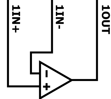
The + input is the “Non-Inverting” input. The – Input is the inverting input. When the + is larger than the -, our output will be positive. If the – terminal is at a higher potential than the + terminal, the output will swing toward the LOW side that we supply to the Op-Amp.
Operational Amplifier Circuit
Consider the following diagram. I generated this diagram with tinkercad. This is a 741 Op-Amp
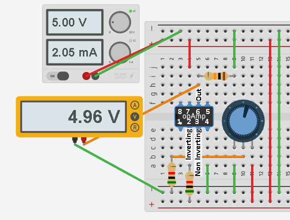
Pin 2 is our inverting input. Our Pin 3 is the non-inverting input. Pin 7 is our HIGH supply voltage, which is 5v. Pin 4 is the LOW supply, which is currently at ground potential. If Pin 2 is higher than Pin 3, the output will be toward ground. If Pin 3 is higher than Pin 2, the output will be positive. Due to the gain of the op-amp, there will be a small range on the potentiometer that is linear. This continues until the op-amp becomes saturated. When the Op-amp becomes saturated, our output will continue to max out at 5v (or very near).
Inverting Circuit (Reference)
Pin 2 will be our reference of about 2.5 volts. Let’s take a closer look at the inverting circuit.
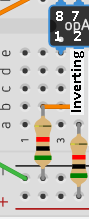
At the right of the image, you will notice a 5K Resistor feeding Pin 2. From Pin 2, we also have another 5K resistor in series that is going to ground. This effectively divides the voltage by 2. Therefore at Pin 2, you will have 2.5 volts.
Non-Inverting Circuit
Let’s look at our variable signal (non-inverting):
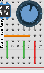
Here, we feed the +5v into the right side of the 10K potentiometer. The other side of the potentiometer is at ground. When the pot is fully counter-clockwise, the wiper will read 0v. When the pot is fully clockwise, the wiper will be at +5v. We still have a voltage divider as before, but this time, we are feeding a variable signal into pin 3.
Operation
Recall that pin 2 is our reference of +2.5v. If pin 3 is below 2.5v, the output will be at ground. When the pot is slightly above 2.5v, the Op-Amp will be in it’s linear region. A small variation in the pot will cause a large variation on the output. Once the pot is turned past the linear region, the op-amp will be in saturation, and the output will max out near 5v.
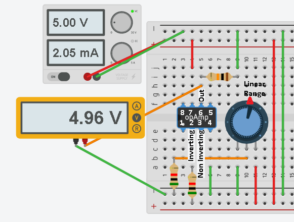
Let’s test our work:
Here, we are past the linear range, so we max out near 5v at this point. The output will stay at 5v from this point, to the remainder of the clockwise range.
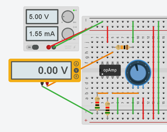
In this example, our pot is turned below 2.5v (half way). This means the inverting input of 2.5v is higher than the non-inverting input. Therefore our output will be at ground.
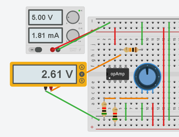
In this last example, we are within the linear operating range, and a very small change in the signal from the pot is providing a huge change in the output. The Op-Amp is acting as a true amplifier.
The gain can be adjusted, and other modes of operating can be achieved by changing the wiring of the circuit and the values of the resistors.
— Ricky Bryce