
Converting a Kenbak-1 Switch Number to Binary
In this section, we’ll be converting a Kenbak-1 Switch Number to Binary. This project is a good example of the Right Shift on the Kenbak-1. Basically, when the user presses a number, we’ll display the binary bit pattern for that switch number.
Mr. Richardson was kind enough to show me some tricks on the Kenbak-1 Emulator’s Memory Loader. This is very helpful for keeping track of your code, for making changes, and for debugging. In this post, I’ll explain the logic step by step. I’ll also post an octal dump if you would like to try this on a hardware emulator.
Keep in mind that on the Kenbak-1 Everything is in OCTAL.
Initialize the Registers
Before diving into the logic, we’ll initialize our registers first. This will make sure all of the registers are in a known state. We’ll also initialize the program counter in memory cell 003 to start at 004.
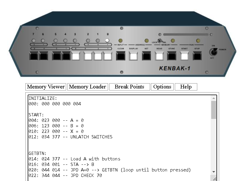
INITIALIZE:
000: 000 000 000 004
START:
004: 023 000 — A = 0
006: 123 000 — B = 0
010: 223 000 — X = 0
012: 034 377 — UNLATCH SWITCHES
Get the Buttons
At this point, we need to get our buttons, and we’ll load them into the A register. If the user does not press a button, we will remain in this loop until we see some input. Later on, we’ll jump to memory cell 044. This will run some checks to see if the button was 0, or 7. If the button was 0, we will turn on all lights. If the button was 7, we will need to take special action later. This is because of the way the right shift works. Otherwise, bit #7 would remain “stale”, and fill all positions with the value of 1.
Here, we simply load the “A” Register with the value of our buttons at register 377. After that, we store the value to B. That way, we can manipulate it without destroying the original value of our buttons.
GETBTN:
014: 024 377 — Load A with buttons
016: 034 001 — STA –> B
020: 044 014 — JPD A=0 –> GETBTN (loop until button pressed)
022: 344 044 — JPD CHECK 70
Find the Bit Position to convert a Kenbak-1 Switch Number to Binary
First, in cell 24, I have a NOOP. This is just to add another line if we need it later on. After that, we start looking for the bit position. Recall that if the user hits button 0, we handle things another way. If the button is 1 through 6, though, we need to find out which one it is. We start shifting the bits to the right, and incrementing the X register each time.
When the value of B hits 0, we know that we have shifted a bit out of the B register. Therefore, the value of X represents the switch number the user pressed. For example: If the user hits button #5, then after 5 shifts, that bit would be out of the B register. At this point the value of the B register is 0. Therefore we can jump to a section of memory to display the X register. This section will be at memory cell 040 (in the next heading).
I’m also running a check to be sure the value of X does not exceed 7. It shouldn’t, except under an unusual circumstance where the operator hits button 7 and another button at the same time. If that’s the case, we’ll just restart the logic. Later on, Memory cell 120 will handle this condition.
At memory cell 036, we just continue our loop until the B register equals 0.
FINDPOS:
024: 200 200 — NOOP
026: 051 200 — RTSFT B
030: 144 040 — JPD B=0 –> FOUND
032: 203 001 — ADD X 1
034: 344 120 — JPD UNC XRUNAWAY
036: 344 026 — JPD UNC FINDPOS+2
When we find a Value for converting a Kenbak-1 Switch Number to Binary
Remember under the last heading, we jump to cell 040 if the B register was empty. This means that we found the position of our bit. At this point, can display this value and restart the program.
FOUND:
040: 234 200 — STX Display
042: 344 004 — JPD UNC START
Check for Buttons 0 or 7
In this case, buttons 0 and 7 are special. We have a separate way to handle those. The problem with displaying 0 is that no lights would be on. The user might think the program is not working. Instead of just leaving the lights off, we’ll turn them all on in the next section of logic at memory cell 70.
Additionally, we treat switch 7 in a special way. After we shift the bits to the right on the Kenbak-1, bit 7 remains “stale”. In other words, if this bit was high, it would leave a trail of 1’s behind it every time we shift our bits. We’ll jump to a special section of memory to handle bit 7 manually in memory cell 100.
In Cell 062, we’ll clear the display until we figure out which bit number the user pressed.
CHECK70:
044: 013 001 — A=A-1
046: 034 150 — STA 150 DEBUG
050: 044 070 — JPD A=0 ZERO
052: 013 177 — A = A – 177
054: 034 151 — STA 151 DEBUG
056: 044 100 — JPD A=0 SEVEN:
060: 023 000 — LDA 0
062: 034 200 — CLEAR DISPLAY
064: 134 000 — STB > A (KEEP A CLEAN)
066: 344 024 — JPD UNC FINDPOS
Handling Button #0 and #7
If we’ve detected that button #0 is high, then we’ll simply turn all of the lights on. After that, we’ll restart our logic. Likewise, if we detect button #7, we’ll simply turn on lights 0, 1, and 2. Then we’ll restart our logic.
ZERO:
070: 023 377 — LDA 377 (All Lights ON) (change 377 to 000 if you want to actually shut off all lights)
072: 034 200 — STA DISPLAY
074: 344 004 — JPD UNC START
076: 000 000
SEVEN:
100: 023 007 — LDA 007
102: 034 200 — STA DISPLAY
104: 344 004 — JPD UNC START
Handling Runway of X
As I said before, there are certain conditions that could cause X to run away, but that should only be able to happen if the user presses more than one button. We will temporarily store X to cell 152 while we check it for an excessive value. If X is OK, then we’ll restore X to what it was, and resume the logic.
XRUNAWAY:
120: 234 152 — STX 152
122: 213 010 — SUB X 10
124: 244 004 — JPD X=0 004 BREAK AND RESTART
126: 224 152 — LDX 152 (RESTORE X)
130: 344 036 — JPD UNC 036 (RESUME)
Full Code
You can paste this code into the Memory Loader of the Kenbak-1 Emulator to try it out! Remember, just be patient after you hit a button.
INITIALIZE:
000: 000 000 000 004

START:
004: 023 000 -- A = 0
006: 123 000 -- B = 0
010: 223 000 -- X = 0
012: 034 377 -- UNLATCH SWITCHES


GETBTN:
014: 024 377 -- Load A with buttons
016: 034 001 -- STA --> B
020: 044 014 -- JPD A=0 --> GETBTN (loop until button pressed)
022: 344 044 -- JPD CHECK 70


FINDPOS:
024: 200 200 -- NOOP
026: 051 200 -- RTSFT B
030: 144 040 -- JPD B=0 --> FOUND
032: 203 001 -- ADD X 1
034: 344 120 -- JPD UNC XRUNAWAY
036: 344 026 -- JPD UNC FINDPOS+2

FOUND:
040: 234 200 -- STX Display
042: 344 004 -- JPD UNC START:

CHECK70:
044: 013 001 -- A=A-1
046: 034 150 -- STA 150 DEBUG
050: 044 070 -- JPD A=0 ZERO
052: 013 177 -- A = A - 177
054: 034 151 -- STA 151 DEBUG
056: 044 100 -- JPD A=0 SEVEN:
060: 023 000 -- LDA 0
062: 034 200 -- CLEAR DISPLAY
064: 134 000 -- STB > A (KEEP A CLEAN)
066: 344 024 -- JPD UNC FINDPOS


ZERO:
070: 023 377 -- LDA 377 (All Lights ON)
072: 034 200 -- STA DISPLAY
074: 344 004 -- JPD UNC START
076: 000 000

SEVEN:
100: 023 007 -- LDA 007
102: 034 200 -- STA DISPLAY
104: 344 004 -- JPD UNC START

XRUNAWAY:
120: 234 152 -- STX 152
122: 213 010 -- SUB X 10
124: 244 004 -- JPD X=0 004 BREAK AND RESTART
126: 224 152 -- LDX 152 (RESTORE X)
130: 344 036 -- JPD UNC 036 (RESUME)
Kenbakuino Octal Dump
If you have a Kenbakuino, then you can use this octal dump. For example, press STOP, then 1 and then SET at the same time for 9600 baud. Be sure you have character and line delays set, though. I set mine up in minicom for 10ms. Remember to change the 377 to 000 at cell 071 if you want all the lights to actually shut off.
000,000,000,004,023,000,123,000,223,000,034,377,024,377,034,001,044,014,344,044,200,200,051,200,144,040,203,001,344,120,344,026,234,200,344,004,013,001,034,150,044,070,013,177,034,151,044,100,023,000,034,200,134,000,344,024,023,377,034,200,344,004,000,000,023,007,034,200,344,004,000,000,000,000,000,000,000,000,000,000,234,152,213,010,244,004,224,152,344,036,sFor more information, visit the Kenbak-1 Category Page!
— Ricky Bryce