
Introduction to ControlLogix Messaging
ControlLogix messaging is used to send or receive information to another processor. In this post, we will receive data from a tag in another ControlLogix processor. Messaging can be used to send or receive information from an SLC-500 or PLC-5 as well. I always recommend reading values from another processor (vs writing). The reason for this is for troubleshooting. If a troubleshooter is tracing through logic, and values are being dumped into the processor, it’s hard to trace where the data is coming from. If the processor is going out to get the data, the troubleshooter will find the MSG instruction when doing a cross-reference.
Another way to transfer data between processors is with the producer/consumer model. The producer/consumer model is scheduled. This means that it updates at regular intervals. Also, it is more efficient with using multi-cast communication when communicating with more than one processor.
The MSG instruction is still used, though when sending or receiving data from older processors. Also, if we only need to gather data one time per day, we would use the MSG instruction. Producer/Consumer update intervals are a maximum of 750ms. Another advantage of the message instruction is that no I/O Configuration is required to make it work. We will specify a path to our target processor without the target processor being in our I/O Configuration tree.
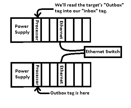
Here is our goal: We will read the target’s “Outbox” tag into our “Inbox” tag.
Configuring the Target Processor
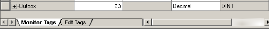
No configuration is required for the target processor (where the “Outbox” tag resides). All we need is a tag that we can read data from (or send data to). For this example, we need a tag in the target processor named “Outbox”. Go to the controller tag database, and in “Edit Tags”, create the Outbox tag as a DINT. I’m also going to place a random value into the outbox tag (in “Monitor Tags” mode), and download the project to the target processor. The target processor is the lower processor in the diagram above. Do not mark it as produced. It’s just a standard DINT that we will be reading a value from. Remember that when you download, your processor will stop executing it’s program! If you are working with a running system, the tag can be created while you are online without the need to download.
Setting up the Initiating Processor
The initiating processor is the processor on the top of the diagram above. Here, we’ll be working with the project of the Initiating processor which will contain the MSG instruction that is getting the data.
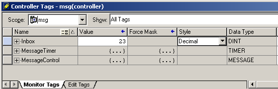
Before we start, let’s create some tags that we will need for this example. Open the controller tag database, and in “Edit Tags” mode, add the following tags. Please pay attention to the data types when you add these tags:
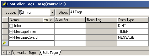
The Inbox is the tag that we will place data into that we get from the target’s Outbox. The MessageTimer will be used in logic to give the message instruction a pulse at regular intervals. MessageControl is the “workspace” for the message instruction. This tag will store the status of the data transfer.
Now, let’s write the logic:
Step 1: Add a self-running timer for ControlLogix Messaging
A self-running timer is a timer that resets itself at regular intervals. I will add this logic to the MainRoutine:
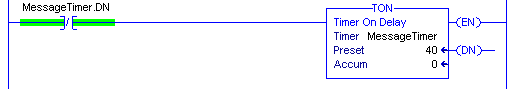
This timer will set it’s DN bit when the accumulator reaches 40ms. When the DN bit is set, the timer resets.
Step 2: Add the MSG instruction
Add the MSG instruction as follows:
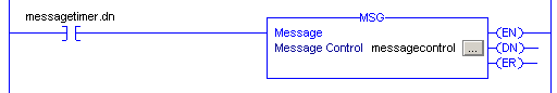
You will notice the Enable (EN) bit, the Done (DN) bit, and the Error (ER) bits to the right. The purpose of the MessageControl tag is to store the status of these bits, as well as other information about the MSG instruction.
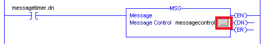
Step 3: Set up the message instruction
Click the “Setup” button within the message instruction. This will bring up the configuration screen.
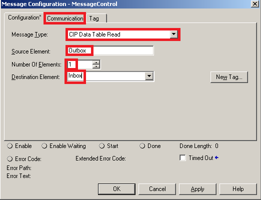
Set up the MSG instruction as follows: We will do a CIP data table read. The source element is “Outbox”. This is the tag in the target processor that we are receiving data from. The destination tag is “Inbox” This is where we place the data we receive from the target’s Outbox tag. When finished, click the “Communication” tab of the setup screen.
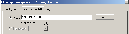
Configure the path for ControlLogix Messaging
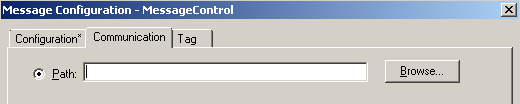
This is the most difficult part of messaging. If the target processor is already in your I/O configuration tree, you could just browse for the processor. In our case, we cannot browse for the processor because it is not in our I/O configuration tree. We will build the path manually.
The problem with placing the target processor in the I/O tree is that communication is constantly on-going to check the health of the modules along the path. Therefore it’s generally more efficient to build the path manually. Once you are used to how the path works, it’s very easy to understand.
Look at our path for the Message Instruction:
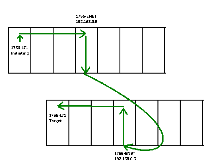
Now look at this diagram to develop our path
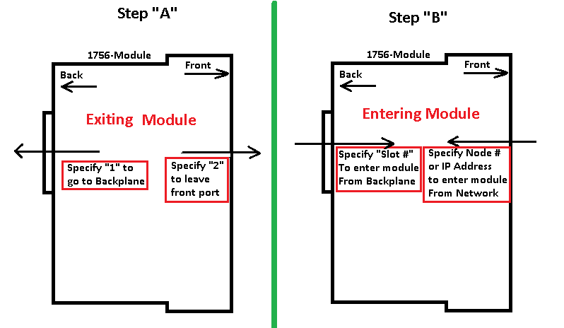
When we build the path, we MUST go from Step A to Step B, then repeat the process until we are at the target.
- From the Initiating L71 processor, look at Step “A”. We must specify “1” to get to the backplane.
- Now that we are on the backplane, look at Step “B”. We specify “3” because that is the Slot # of our ENBT module.
- We are on the ENBT module now, and back on Step “A”, so we specify “2” to come out the front port.
- Back on Step “B”, we will be going into the ENBT on the target chassis, so specify the IP of the target module, “192.168.0.6”
- Now that we are on the ENBT module, back on Step “A”, specify “1” to get to the backplane.
- To enter the processor from the backplane (Step “B”), specify “0” for the processor slot #.
The path will be “1, 3, 2, 192.168.0.6, 1, 0” Go through those steps a few more times until you are comfortable and understand how we got this path. Each of the green arrows represent a step in building the path to the target processor.
Now let’s enter this path into our MSG Instruction.
Test your work for ControlLogix Messaging
Next, I’ll download to the processor, then we’ll verify the Inbox tag of the Initiating processor matches the Outbox tag of the target processor.
Hint: to transfer larger amounts of data, you could use an Array. Instead of a single DINT for the inbox and outbox, we could use DINT[10] as the data type, and change our number of elements to 10 on the “Configuration” tab of the MSG instruction.
Check out this link if you are interested in learning how to message over DH+ to the older processors. Another resource to check out is DF1 Messaging. Additionally, you can check out the post on SLC-500 Messaging. On the other hand, if your SLC-500 needs to initiate a message to the ControlLogix, I have a post for that as well. Lastly, I’ve done a speed test on the message response time.
For more information, visit the ControlLogix post page!
— Ricky Bryce
Pingback: Resetting fuses on the ControlLogix 1756-OB16E module.
So how would you setup your path if you had a
L73 processor in slot 0
ENBT in slot 4
SLC 5/05 in Slot 0 with ip address of 192.168.10.204
I have tried 1,4,2,192.168.10.204. Doesnt seem to be working on this particular processor. I have done this on two other processors with no problems. but this one is being more hardheaded for some reason. Any Ideas?
Your path looks good. You might look at the control tag for the message block to see what error you are getting. If you see an error code, go to the instruction help for the message instruction. At the bottom of the help file there is a link to the error codes. That should tell you why it’s failing.
Are you doing an SLC typed write, or a word range write (or read)? You have to be careful because the word length might not mach up if you are sending a DINT to the SLC (which is 16 bit).
Let me know how it goes!
Ricky
On another note, Adam — I’m sure you know this… Be sure the ENBT has an IP address that is in the same subnet as your SLC. When your PC is on the same network, be sure you can ping both the SLC and the ENBT. Be sure the message length does not exceed the number of elements that are available on the source and target device. If all of that is in place, I don’t see why it wouldn’t work. — Ricky
Hi Adam,
Try add 1,0 at the end of your path.
1,4,2,192.168.10.204,1,0
Anyway worked for me.
Thanks, Mat… You are correct if the target was a ControlLogix processor. In ControlLogix, he would be accessing the ENBT by it’s IP address, but then would need to enter 1 to get to the backplane, and 0 if the processor was in slot 0. In this case, Adam is going to an SLC 5/05, which has an Ethernet port built into the processor. So once he’s at the IP address, he’s achieved the target device. His path should be correct for a 5/05, but I would be curious to see what the error code is in the message control block. As long as the routine the MSG instruction is in, and it’s being executed at regular intervals, he should be getting that error code, which would tell us more information for sure! — Ricky
Pingback: ControlLogix DF1 Messaging to SLC 500 - Bryce Automation
When I replace my ethernet card and assign a new IP, how can I change the path?
You wouldn’t need to change the path of the message instruction if the new ENBT (or other 1756 Ethernet module) is in the same slot, and your message is going to the same place. If, for some reason, you do need to modify the path, just click the ellipsis (three dots) on the MSG instruction face in logic, and go to the “Communication” Tab. The ControlLogix Messaging post will help you to build the new path, and has some good examples. Let me know if you have any questions on this.
So how would you setup your path if you had a
L75 processor in slot 0
EN2TRin slot 1
Other end prosoft module PLX31-EIP-MBS4 ethernet port 1
192.168.1.4
How to set path… any idea give me.
I believe the PLX31-EIP-MBS4 is a modbus to serial gateway. In that case, it would be modbus devices you want to access right? If I’m understanding correctly, your configuration would not be with the MSG instruction. Check out this video by Prosoft. https://www.youtube.com/watch?v=7_pOhn45OdA Hopefully, that will get you pointed in the right direction. — Ricky
Good day, how do you multihop when the Ethernet modules are sitting on different subnets? Example, 1st EN2T has IP address 172.25.172.68, and the other has address 172.25.154.50. Can you multihop this, and how?
Hello Hans. Let’s say, we have a processor in slot 0, and an EN2T in slot 1 of the local chassis with an IP of 172.25.172.67.
Next, we’ll say we have a second chassis with an EN2T in slot 5 with an IP of 172.25.172.68. Slot 6 has a second ENT2 with an IP address of 172.25.154.50. We have a third chassis with a processor in slot 0, and an EN2T in slot 1 with an IP address of 172.25.154.51. We want to send a message from the processor in the first chassis to the processor in the third chassis. Look at steps A and B on the documentation. You just work your way back and forth between A and B to get to your target. The path would be 1,1,2,172.25.172.68,1,6,2,172.25.154.51,1,0
To start, we have 1,1,2. This gets us to the backplane, then to slot 1, and out the front port.
Next, we specify the target IP, which is 172.25.172.68, then we go to the backplane with 1, and then 6 to slot 6.
At this point, we come out the front port with a 2, then go to the IP 172.25.154.51.
At last, we go 1 to the backplane, then 0 to slot 0.
Hope that gets you going!
Ricky