
Introduction for Proportional Settings for ControlLogix PID Enhanced (PIDE)
In this section, we’ll discuss the proportional settings for Controllogix PID Enhanced (PIDE). It’s important to remember the difference between the PID in ladder logic vs. the function block PIDE. The main difference is that the ladder logic PID instruction is position based. The Function block PIDE is velocity based. This means that in a velocity based PID, or changes basically take place from that point on.
The output from proportional is generally based on error. However in a velocity based PID, the output is based on the change in the error. Later on, we’ll demonstrate this.
Function block PIDE
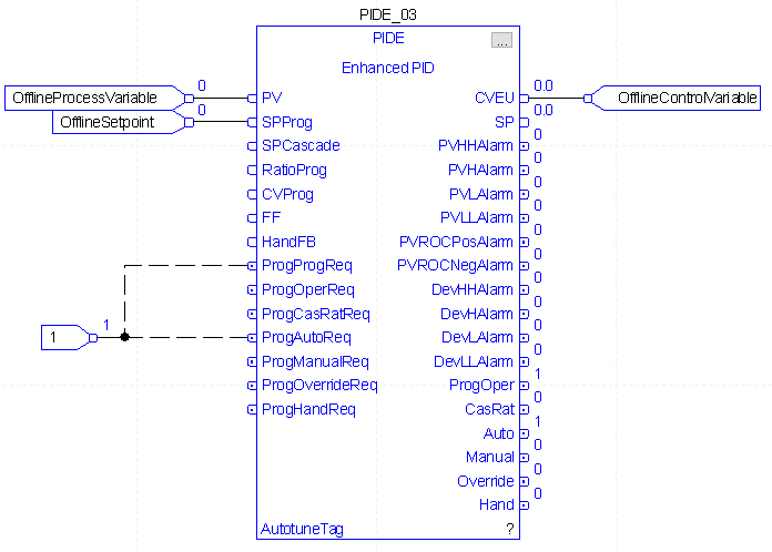
To demonstrate, we’ll look at a PIDE instruction. Realize this PID is not attached to any process at this time. The purpose of this PIDE is for us to simply plug in numbers. After that, we can observe how the output responds. To summarize, this PID is forced to program control mode (in auto). We simply send it a set point and a process variable (feedback) to observe the change in the output. All scaling for this PIDe is 0 to 100%, and the PIDE is in “Independent Mode”. This means it will calculate proportional, integral, and derivative separately. It’s also “reverse acting” to simulate a heating process for example. Think of the Control Variable as an output to heating bands. The process variable is the feedback, or the temperature of the process. Our set point is the temperature we want to achieve.
Offline Experiment with Gain of 1
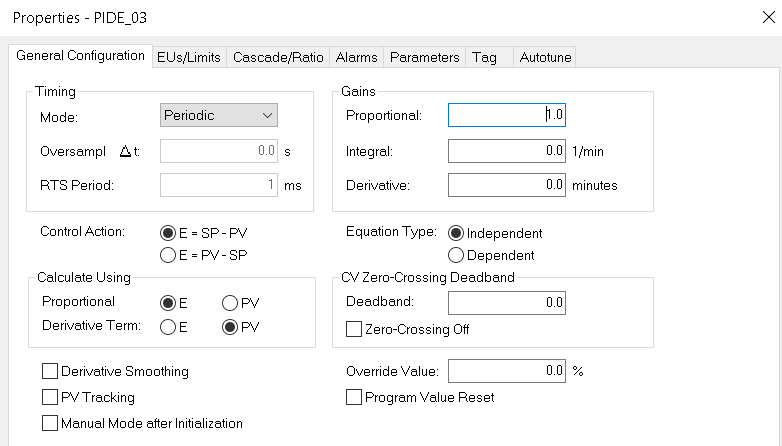
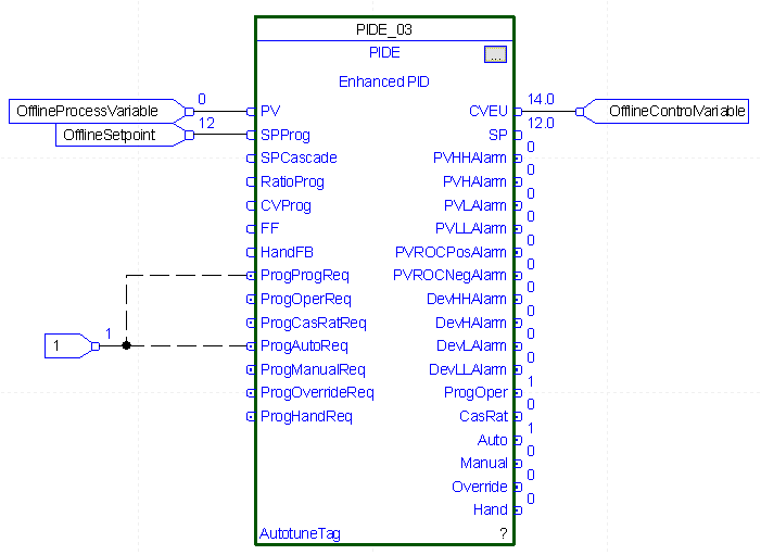
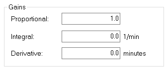
Let’s set the Proportional gain to 1. For the purpose of this demonstration, we’ll leave the Integral and derivative settings at 0.
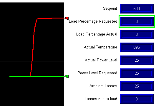
Let’s change the Set Point to 10, and observe the output.
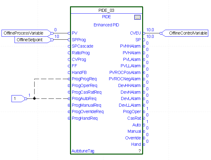
Obviously, the output went to 10, because we have 10% error with a gain of 1. (Gain X Error).
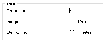
Changing the Gain to 2
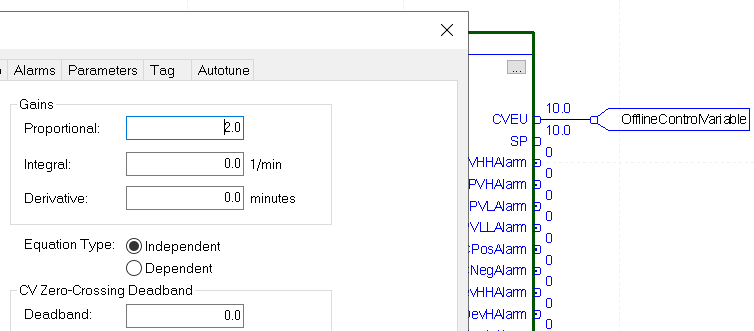
At this point, we’ll understand the difference between a Position based, and a velocity based controller. In a Position based controller, when we change the gain to 2, we would expect the output to immediately go to 20. However, when we change the gain to 2 in this velocity based controller, nothing happens. The output is still 10 because there has been no change in the error. This is one advantage of a velocity based controller, because we did not immediately “bump” the process.
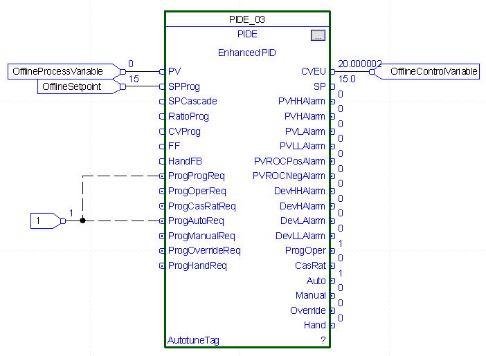
At this time, let’s change the set point to 12.
In position based control, the total output would be 24%. Because this controller is velocity based, our output is 14%. This is because we started with 10% output, and our change in error was 2% with a controller gain of 2. This is a 2% INCREASE in error times the Proportional gain of 2. Since we started with an output of 10, the controller added 4% because of the change, and our output is 14%.
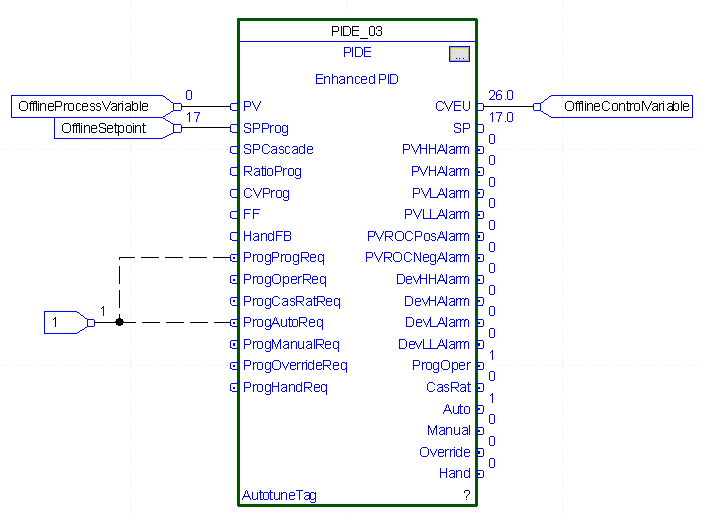
That being said, let’s increase the set point to 15.
Our output goes to 20% (not 30!). Because our error changed by 3% (times 2% gain), we add 6% to the previous output of 14%. The output is 20%.
Changing the Gain to 3
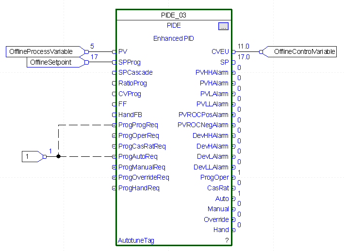
To be sure you understand the effects of Proportional gain, let’s do a couple more experiments. Remember our current output is 20%. I’m going to set Proportional gain to 3, and increase the set point to 17 (from 15). This would cause a 2% increase in error (times the gain of 3), which would result in a 6% increase in output. The output goes to 20%.
Finally, one last experiment. With the Proportional gain at 3, I’ll increase the PROCESS variable to 5%. This will cause the error to drop by 5%, therefore the output (control variable) will drop by 15%. Our new output is 11%.
Now that you understand how the proportional gain works, let’s try to find a good setting in a real world process.
Online Proportional Settings for ControlLogix PID Enhanced
One method of tuning is to increase the Proportional gain, and cause disturbances in the loop. At some point, the increase in proportional gain will cause continuous oscillations in the loop. At this point, we record the natural period of the oscillations, and cut the proportional gain in half. We will use the natural period to tune other parameters in another post, such as Integral, and Derivative. A least this gives us a starting point for the PID settings. You cannot always use this method in a running process. With this in mind, let’s give it a shot on a heating process. We’re going to use a different PIDE for this that is attached to a simulated real world process.
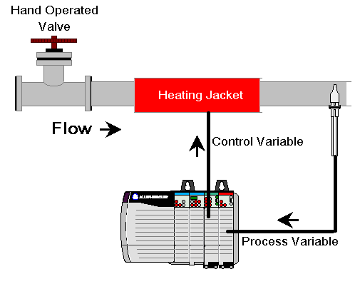
Now, let’s consider an online heating process. Realize the settings we use here are for example only. The settings on your equipment could vary widely. The purpose of this exercise is simply to understand the effects of proportional gain. In this case, we have a manually (hand) operated valve. There is nothing automatic about the valve. By changing the position of the valve, we change the amount of heat we remove from the system. Cold liquid will flow toward the heat bands, and we are attempting to keep the temperature of that liquid constant.
Proportional Gain of 1 (online)
With our proportional gain at 1, we’ll cause a disturbance in a heating process by shutting the valve. I’ll start off at the set point, and we’ll see what happens. We are seeing a graph of the set point (in green), and the Process Variable (in red). We are starting at 1, but on an unknown system, you might want to start at 0.1, and then double that for each disturbance to observe the effects of your changes. Again, this method might not work in every situation, and could be even dangerous in some scenarios. These examples are just to understand the effects of the changes only.
Notice that when we shut the valve, the temperature increased as expected. It did stabilize however. Remember that for tuning, we are looking for the value that will cause oscillations. We are not at the set point, because at this point we only have proportional gain. Later on, when we add Integral, we’ll always be able to get back to the setpoint.
Proportional Gain of 2 (online)
Go back to 100% load to get our process variable back to the set point. Now, let’s double the controller gain, and observe the effects of our change.
You can see that we had a little more instability, but all in all, our process variable did level out.
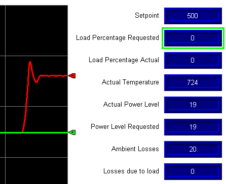
Proportional Gain of 3 (online)
Since we are starting to cause some instability, let’s go to 100% load to get back to the set point. Then increase the gain to 3, and observe the effects.
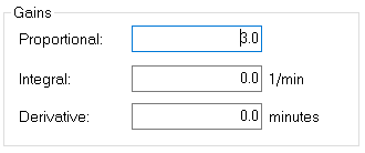
As you can see, we are now experiencing continuous oscillations. Therefore, we will cut the Proportional gain in half, and write down the natural period. The natural period is peak to peak or trough to trough. This is around 30 seconds, or 1/2 minute. We’ll use this value as a starting point when we set up integral and derivative (if used).
Summary of Proportional Settings for ControlLogix PID
Remember the output of this proportional controller is based on two main factors. Change in error, and the gain. Our goal for tuning proportional is to increase the gain until we see continuous oscillations during a disturbance. We’ll then write down the natural period, and set the controller gain to half of this value.
You can research other tuning methods to find one that suits your purpose best. Always take care to fully understand the effects that a change in these values will have on your system, and the associated dangers.
In this case, we were not able to achieve the set point, but that will happen as soon as we add Integral, so check out the post on integral settings!.
— Ricky Bryce