
Introduction to PlantPAx 4 Control Valve
The PlantPAx 4 control valve object allows us to control the position of a valve, and monitor it’s status. Obviously, we need to send the valve a command, and read the process variable to be sure it is in position. In detail, we’ll walk through the steps of importing the logic, and adding the display to our HMI. Remember that this document is for training purposes only and is not actually attached to any prime movers.
Adding the logic
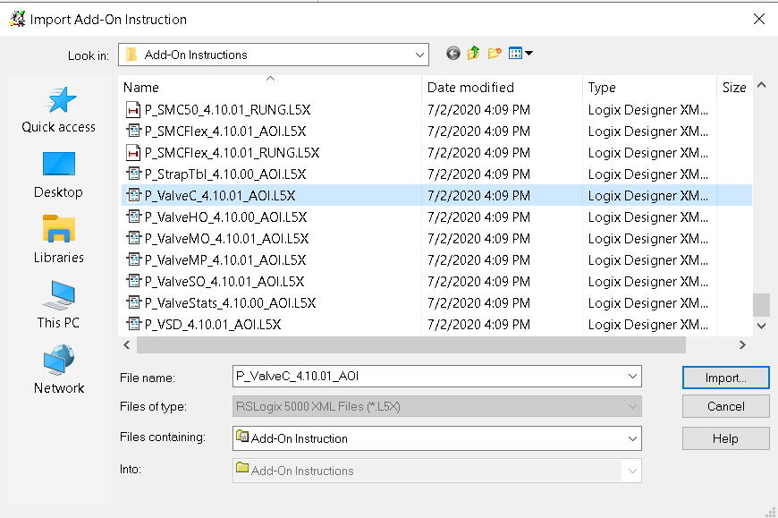
Our first step will be to import the add-on instruction to allow the control valve to work. With this in mind, right-click “Add on Instructions”. Select “Import Add-On Instruction”. The instruction we need to import is called “P_ValveC”. We’ll leave all options at default when we import the instruction.
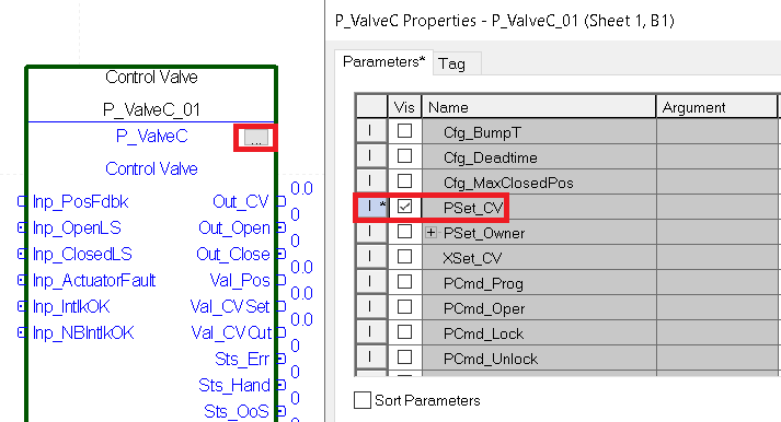
Next, click the ellipsis, and make the PSet_Cv visible. This will allow us to tie a tag into the instruction to control the valve.
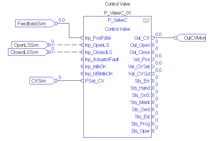
Finally, we’ll set up the logic for the P_ValveC instruction. Let’s create some tags to be able to simulate real switches, feedback, the output, and the control command. We’ll just make them as controller tags so they are easy to access. Then, add the logic as shown.
- FeedbackSim as DINT
- OpenLSSim as BOOL
- ClosedLSSim as BOOL
- CVSim as DINT
- OutCVMon as DINT
Download your work and take the processor to run mode.
Add the Faceplates
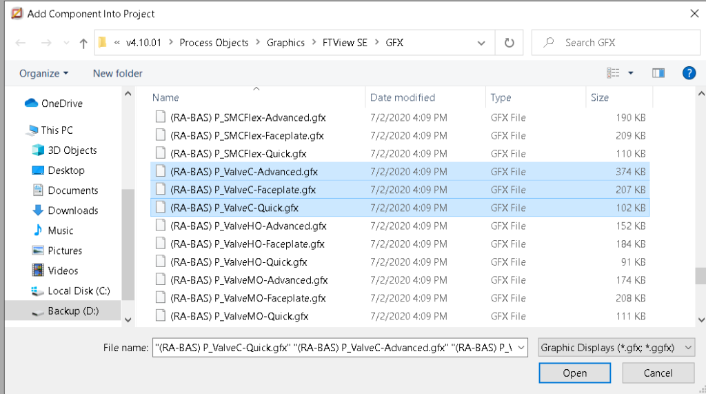
Our next step is to add the faceplates to our HMI project. Right click “Displays” under “Graphics”, and choose to “Import component into application”.
At this time, we need to import the faceplates: P_ValveC-Advanced, P_ValveC-Faceplate, and P_ValveC-Quick. Hold CTRL to select these faceplates, then press “Open”.
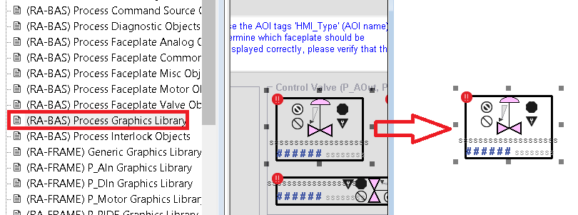
Next, we are ready to add the global P_ValveC object to a display screen.
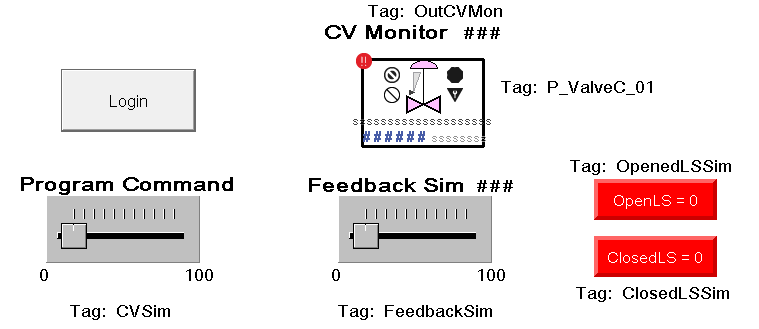
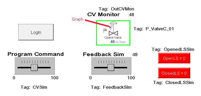
At this time, we’ll add other objects to the display to complete our simulation. Be sure you have a login button, two maintained pushbuttons, Two horizontal silders, two numeric displays, as well as the P_ValveC object. In this case, we will scale the sliders from 0 to 100.
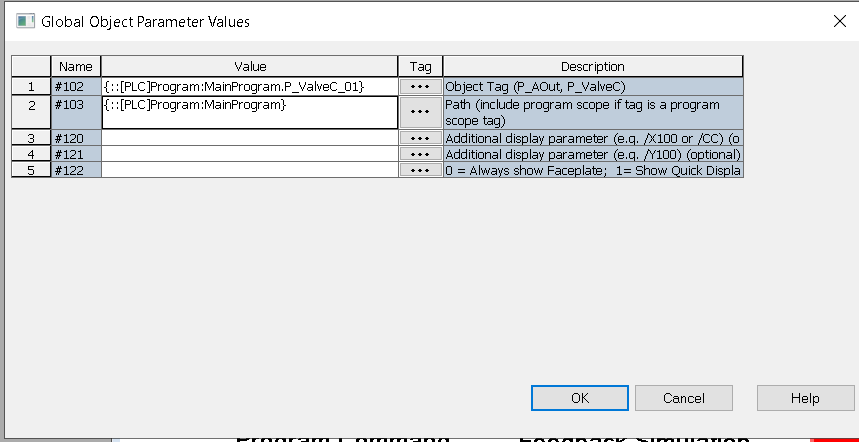
Don’t forget to set the global object parameter values of the valve. To do this right-click the valve object, and set parameter #102 as P_ValveC_01. Parameter #102 is the scope, which is the folder the valve is in.
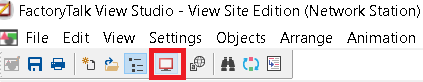
Close your display, and save the changes. Be sure you have a way to get to the display that the P_ValveC object is in. Launch the SE Client.
Configure the display object
Next, be sure to log in, and double click the P_ValveC object. Put the valve in program control mode. Go to Maintenance, Display Advanced Properties, and into HMI Configuration. Set the label and the tag.
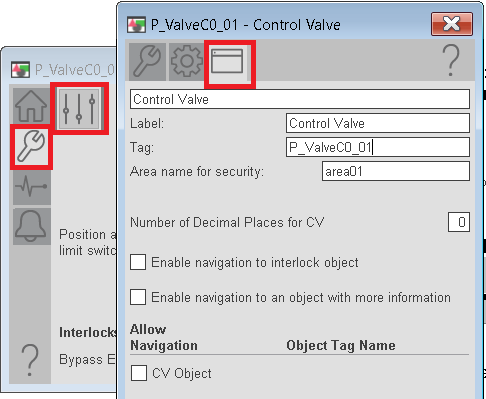
In this case, we don’t have any other objects to attach. However, if you have other objects, be sure to enable navigation to those objects.
Also, take a look at the Engineering and Maintenance tabs to see if there are other settings you need to enter.
You are now ready to experiment with the object. Notice the valve has a graph to indicate the position. Change the command, then slide the feedback to match the command. Notice the different shades on the valve when it is in position, and out of position.
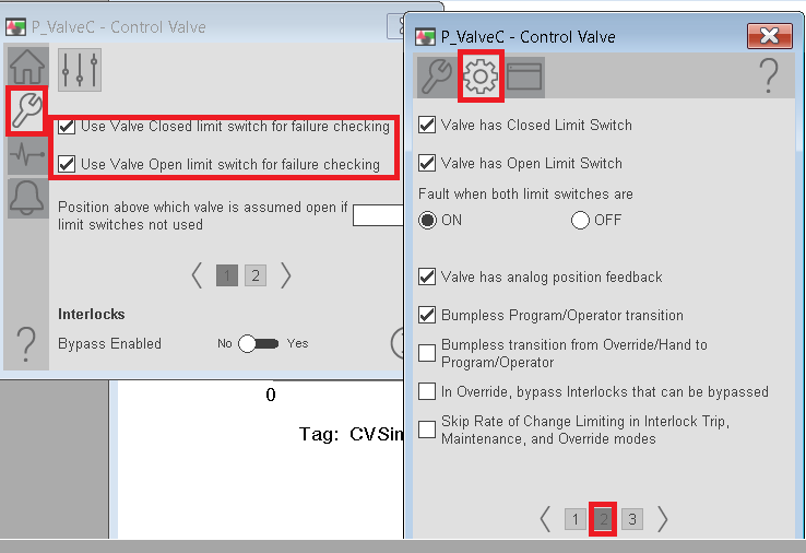
Note: If you wish to use the limit switches for error checking, we must turn this feature on.
For more information, visit the PlantPAx category page.
— Ricky Bryce