
Introduction to Capacitance
Capacitance opposes a change in voltage. The unit for a capcitor is a “Farad”. We use capacitors to filter the “ripple” effect when converting AC to DC. We will also use capacitors in resonator circuits, such as a tuner for an AM or FM radio. Any time you have two conductors separated by an insulator, you have capacitance. Sometimes, however, you might have unwanted capacitance in a circuit. For example, you have a communication cable. In a communication cable, we need the bits to go from high to low. We need this to happen very quickly. If we have a long cable, with a lot of capacitance, this will slow our communication speed.
Let’s look at a pure AC signal. I’m generating these images using tinkercad.
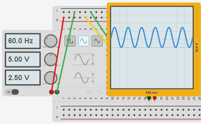
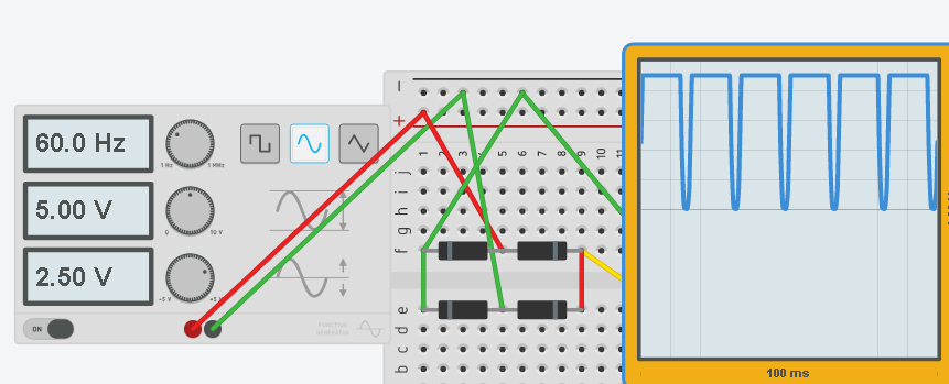
Now, let’s rectify this signal. The voltage is not going negative, however, we do have a little bit of “Ripple” effect. We should smooth this out.
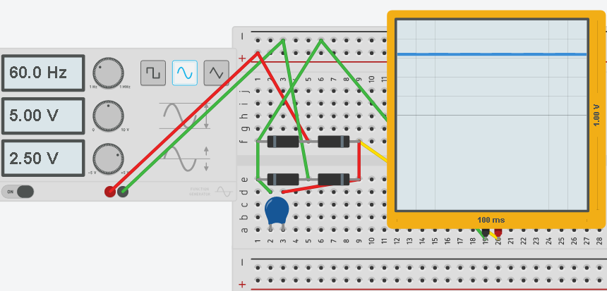
At this point, we will place a 10 MicroFarad capacitor on the output of the rectifier. You will see that we have a nearly pure DC output now, even though our source is 60Hz AC.
Calculations
Sometimes, it becomes necessary to make a certain capacitance value from various capacitors that you may have laying around your shop. Let’s look at how we would calculate a certain capacitance value from multiple capacitors that are connected together in series or in parallel. It’s important to realize that calculating capacitance is different than calculating resistance.
When calculating capacitors in parallel, we just add the values together. Here is an example:
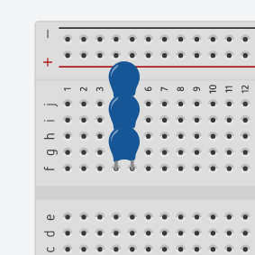
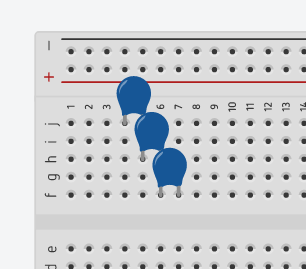
Here, there are three capacitors in parallel. These are 22pf capacitors. For capacitors in parallel, we simply add the values together to derive the total capacitance. Obviously, in this case our total capacitance is 66pf.
When using capacitors in series, things are a little bit more complicated. Let’s look at another example using the same 22pf capacitors.
The formula for calculating the capacitors in series is: 1/C1 + 1/C2 + 1/C3 ……… = 1/Ct
Therefore 1/22pf + 1/22pf + 1/22pf = 3/22pf
This means that the total capacitance is 22pf/3 or 7.3333 pf
Be aware in this example, we are using ceramic capacitors. Ceramic capacitors do not care about polarity. This means that it does not matter how we place the capacitors into the circuit.
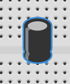
You are also going to come across electrolytic capacitors. Electrolytic capacitors are polarized, and you must place them in the circuit with the correct polarity!!! The capacitor can (and likely will) explode if you reverse the polarity. Electrolytic capacitors have clear markings as to which lead is the – (negative) lead.
In some cases, capacitors work with Inductors. Check out the post on inductors using this link!
— Ricky Bryce
Pingback: Building a Piont Contact Diode to be used in a radio receiver circuit.
Pingback: Example of an inductor and how to calculate total inductance.
Pingback: Overview of the Schmitt Trigger, and a practical application.
Pingback: Inductance Calculations in Series and parallel circuits.