
Introduction to Integral Settings for ControlLogix PID Enhanced (PIDE)
In this section, we’ll discuss the effects of Integral Settings for ControlLogix PID Enhanced. Integral is based on 2 main factors (aside from the gain): The amount of error and time. Moreover, with the PIDE, when we change the Integral gain, you are changing the number of repeats per minute. A repeat is based on error. For example, if you start with 10% error, and have an Integral gain of 1, after one minute, your total output will be 20%. I want to emphasize that this procedure is for example only, and could be dangerous at your location, depending on the type of equipment you have. Always use full precautions, especially when making any changes.
In the last section, we talked about Proportional Gain. Most controllers are simply “PI” controllers. This means they are based on Proportional and Integral, working together to achieve a set point. In other words, derivative is seldom used.
Observing Integral Settings for ControlLogix PID (offline experiments)
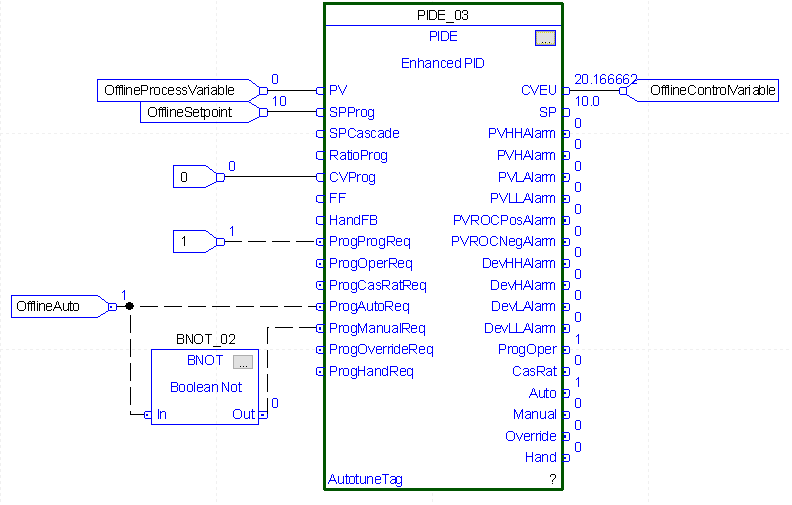
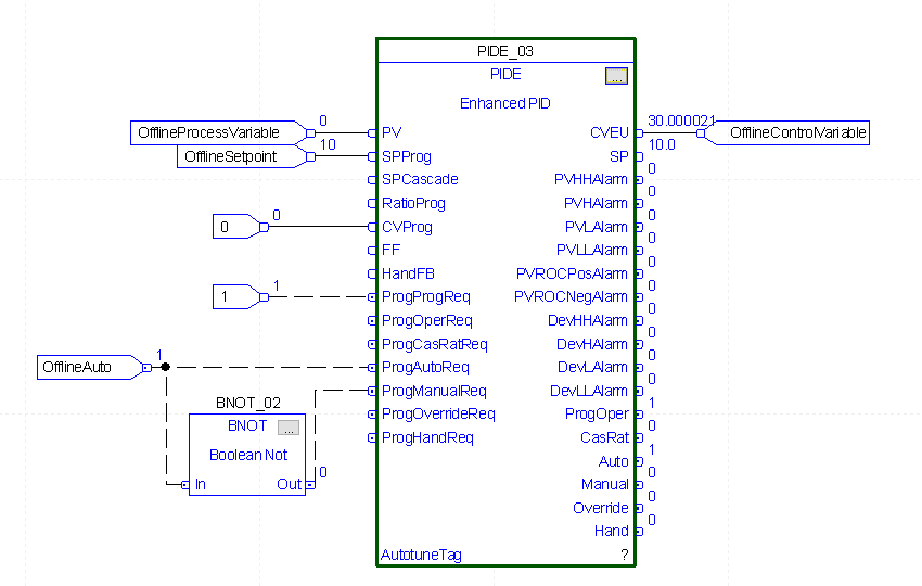
In this case, we have an offline PID controller set up. The purpose of this PID is for us to simply put values in for a set point and process variable (pv). The PID is set up in Independent mode, and is reverse acting.
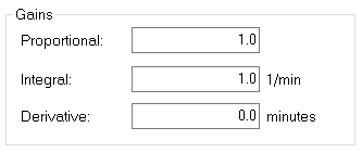
We’ll set the Proportional Gain to 1. With the set point at 10%, we will have 10% error as the starting point. Watch what happens after 1 minute, if I set the Integral gain to 1.
As you can see in the PID instruction, after 1 minute, our output was 20 as expected.
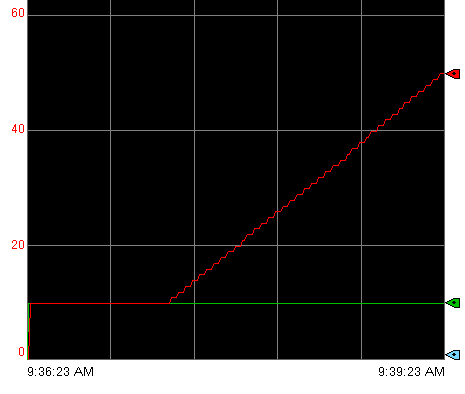
In our graph, we see that after 1 minute, we had 20% output as expected, but I’ve continued this for 2 minutes. After 2 minutes, we had another repeat, so our output was 30%.
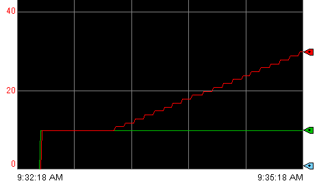
We are only able to predict this because this is an offline PID just for us to observe the output. The process variable is not changing. In reality, an increase in output would cause less of an error to repeat. In other words, in reality, we are still adding the error to the output at a rate of 1 per minute. As our error decreases, though, our repeat has less value. Therefore, CV will still increase, but at a slower rate.
Integral Gain of 2
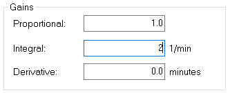
At this time, let’s look at an Integral gain of 2. Since the process variable is not changing, and we have 10% error, we would expect the influence of integral to be doubled. We start with 10% output based on proportional only. Our error is constantly 10%. With an Integral gain of 2, this gives us 2 repeats per minute, or 20% per minute (10% x 2 repeats within a minute).
By observing the PIDE instruction, after 1 minute, the output went to 30% as expected.
Here we have a graph over a 3 minute period. With Proportional gain at 1, the control variable (in red) was at 10%, which is because the error was 10%. With an Integral gain of 2, every minute, we add 20%. After 2 minutes, the total output is 50%.
As you can see, we added more to the output, and made it more aggressive compared to the previous integral setting of 1. In an actual process, though, if we get the Integral setting too high, it will become unstable.
Tuning the Integral Parameter
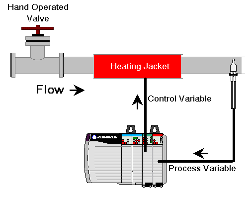
In the last post, we talked about gain based on change in proportion. The controller provided an output to heating bands to control the temperature of a liquid flowing through a pipe.
We also saw that proportional gain only did not hold the process variable at the set point. At this time, we’ll add an integral value to achieve the set point.
When tuning the proportional value, we increased the gain step by step and caused disturbances. Our goal in doing that was to find the value for Proportional gain that caused oscillations. Then, we recorded the natural period of those oscillations. We’ll use that natural period to find a good setting for integral gain. The formula I use is: Proportional gain / natural period. The proportional gain is currently 1.5, and the natural period we found was 30 seconds, or .5 minutes. This should give us an integral value of 3 repeats per minute.
In our real, online PIDE instruction, we’ll set the integral gain to 3, and cause some disturbances to observe the effects.
Observing Integral Settings for ControlLogix PID (online experiments)
Earlier in this section, we experimented with a PID that was not connected to a process. Now, we’ll be using a PID that is controlling a heating process. Remember, our goal is to achieve the set point. Having a good Proportional and Integral setting should make that happen.
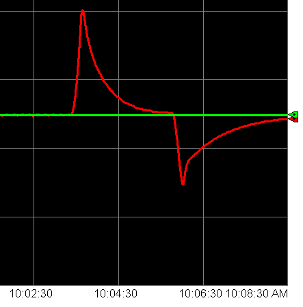
First, let’s shut the valve. The temperature will spike, but we will come back to the set point. This time, we will focus on the Process Variable. The process variable is in red this time, and our green line is the setpoint.
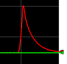
Now, we’ll open the valve. This will result in a fast drop in temperature. When that happens, the controller will provide more output to the heating bands. Let’s compare both disturbances below. On the left, we see the disturbance when the valve closed, and on the right when it opened.
That’s a good response Out of curiosity, let’s double the integral setting, and see if anything changes.
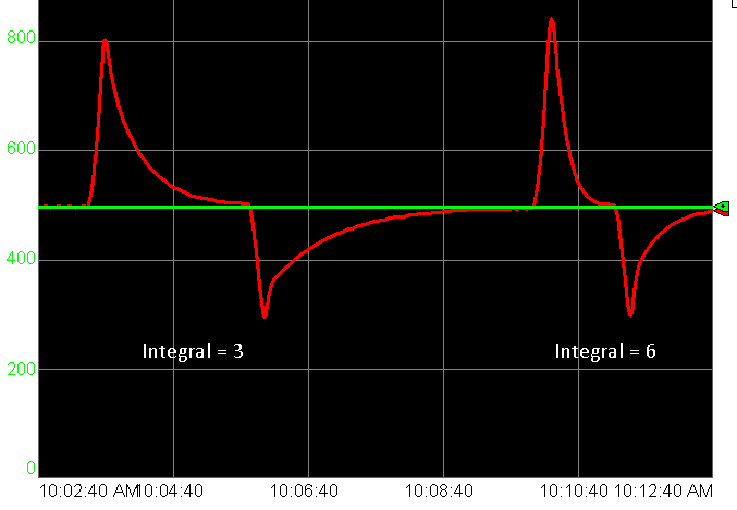
You can see that when we double the Integral, the temperature spikes higher, but the loop responds faster. Be careful, though about increasing integral. If we get the integral set too high, the loop will become unstable.
Now let’s try integral at half the recommended setting.
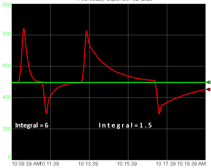
We see that it’s much less aggressive, and responds much more slowly!
For more information on ControlLogix, visit the category page!
— Ricky Bryce