
Introduction to Counters in the SLC-500 processor
Counters in the SLC-500 work in a similar way to some external hardware counters. Each time the rung goes true, the counter is activated, and the accumulator value will change by 1 count. There are two types of counters: the Up Counter (CTU) and the Down Counter (CTD).
Practical examples of how a counter is used:
- Counting machine hours
- Coutning motor starts — If the operator attempts to start a motor more than a few times in an hour, they are locked out from starting the motor until enough time has passed for the coils to cool off.
- Counting machine cycles (This could indicate the amount of product produced)
- When the CTU and CTD are used in combination, we can know how many parts are in a certain zone of a conveyor. Each time a product enters a zone, the accumulator increases…. Likewise, each time a product leaves the zone, the accumulator decreases. The accumulated value would represent the number of parts within that zone.
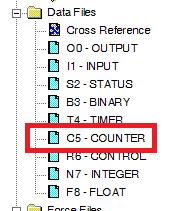
The Counter File
First, let’s take a look at the data file that stores counters by default. This is data file C5.
Let’s open the data file to see the components of a counter. Here, we only have one counter. If you need more than one counter, you can drop offline, and go to properties to increase the number of elements. Be aware that if you make offline changes, you must download. Be aware that downloading will take the processor out of run mode.
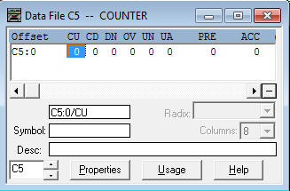
- The CU bit is the count up bit. This bit goes true when the CTU instruction is enabled. When the CU bit goes from false to true, the accumlated value increases by 1 count.
- Similarly, the CD bit is the count down bit. When the CTD instruction goes true, the accumulated value decreases by one count.
- However, the DN bit is the Done bit. When the accumulated value is equal to, or above the preset, the DN bit is true.
- The OV bit is the Overflow bit. Be aware, there are some misconceptions on this bit. This does not go true until the accumulated reaches 32767, and then counts up one more count. (The count will no longer be accurate) This is the maximum value for a 16 bit signed integer.
- Likewise, the UN bit is the Underflow bit. This goes true when the CTD instruction trues to lower the accumulated value below -32768. (Again, the count will no longer reflect the true accumulated value)
- The UA bit (Unload accumulator) bit is for High Speed Counters. We will not discuss this bit in this document.
Counter Logic
Next, we will look at a logic example:
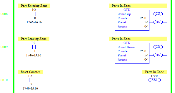
In this example, each time a part enters a zone, switch I:2/0 will detect the part, and increase the accumulator. Each time a pert leaves the zone, I:2/1 will decrease the accumulated value.
If we need to clear all of the parts from the conveyor, we can wire a reset button to I:2/2 to reset the counter to zero.
Notice that we use C5:0 for both the CTU and the CTD. You won’t always see a CTD instruction used. If you have a CTD instruction in your logic, it’s almost always associated with a CTU instruction. C5:0 is our counter. It’s just that the CTU instruction increases the accumulator, and the CTD instruction decreases the accumulator.
For other posts on the SLC-500, please visit the Category Page!
— Ricky Bryce