
Introduction to ControlLogix Function blocks
ControlLogix Function Blocks show the flow of information graphically. Analog programming is very easy to follow using this method. Discrete (on/off) logic can also be used in Function Block programming. When you create a new routine, you can declare it as a function block type. In this post, we will start off with some discrete logic. Once you understand how the discrete logic works, you shouldn’t have any trouble implementing function blocks with analog values as well. I will assume that you are working with a test processor in a non-production environment. This way, we can experiment with the logic without worrying about damaging our system or personnel.
Create the routine for ControlLogix Function Blocks
In this step, I will right-click on the MainProgram to set up a new routine.
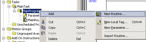
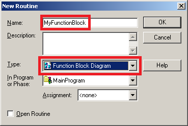
Next, we must name the routine “MyFunctionBlock”. Be sure to select “Function Block Diagram” as the type, then press OK.
Since “MyFunctionBlock” is a subroutine, we must jump to the subroutine from the MainRoutine. Open the MainRoutine, and add your JSR instruction as shown.
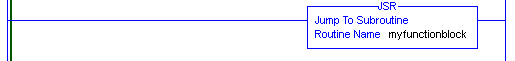
Your routine is now created and executing!
Input and Output References
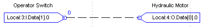
Function Blocks use an Input Reference (IREF), and an Output Reference (OREF) to pass and receive values from tags. Consider the following rung of logic. Our goal would be to convert this rung of ladder logic into a function block.
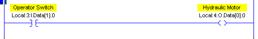
Here, we can see that we have one input and one output. The input output references have tags associated with them. When the Operator Switch equals 1, we want the Hydraulic Motor to equal 1 also.
Open the “MyFunctionBlock” Routine by double-clicking “MyFunctionBlock” in the Controller Organizer window. Place an IREF and an OREF onto your Function Block sheet as shown. You can drag these instructions down from the Instruction Toolbar, or right-click any blank area on your function block diagram and choose “Add Element” to add both instructions.
You will immediately notice question marks on the IREF and OREF instructions. This is because these instructions need to be associated with tags. Assign the tags, and draw the connection between the IREF and OREF as shown.
Test your work. You will see that when the operator switch is off, a “0” is sent to the Hydraulic motor. When the operator switch is on, a “1” is sent to the hydraulic motor. Notice the connection element is a dashed line, which indicates discrete (on/off) data.
BNOT Instruction
Now that you know how Input and Output references work, let’s check out another line of logic.
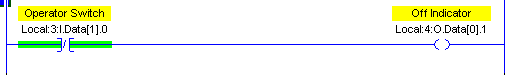
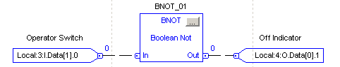
This time, it’s not as easy as just drawing the IREF to the OREF. We need to manipulate the value before it’s sent to the output. When our switch is on, we want a “0” to be sent to the output. When the switch is ON, we want a “1” to be sent. We will need a “Boolean NOT” (BNOT) between the input and output references to reverse the logic. I will create this on a new sheet. You can create a new sheet by clicking the “Add Sheet” icon at the top of your function block window. Your logic will appear as follows:
BAND Instruction
The next instruction we will cover is the Boolean AND (BAND). The BAND instruction will provide an output of “1” when all of the conditions attached to the instruction are true.
Consider the following logic:

To convert this into a function block, we will need three IREF instructions, and OREF, and a BAND instruction. Organize your logic as shown:
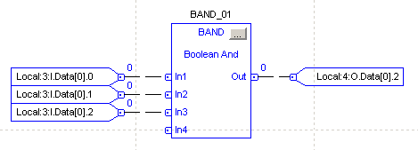
If you wish to add or remove some of the inputs, click the configuration button within the BAND instruction. In this case, all three inputs must be true in order to provide an output.
BOR Instruction
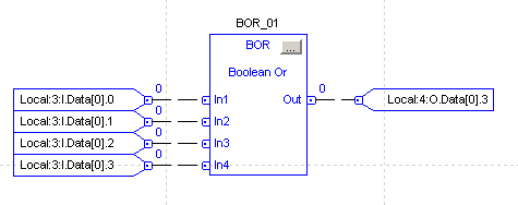
Next, is the Boolean OR (BOR) instruction. Look at the line of logic below that we will be converting into a function block.
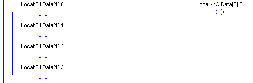
Notice this time that ANY of the inputs can go true to give us an output. We will convert this to a function block as follows:
Putting it all together
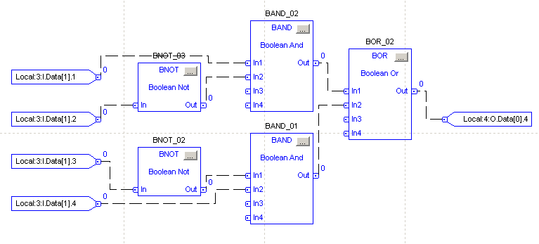
Now that you understand how the basic instructions work, consider this rung:
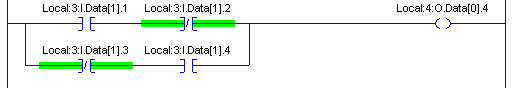
Here is where things get a little bit cumbersome. This rung would convert to an FBD as follows:
Now that you understand how function block diagrams are working, you can use them in your projects. To see all of the instructions that are available, you can use the help file.
Summary of ControlLogix Function Blocks
In summary, Function blocks will graphically show the flow of information. This is becoming more common for analog values. For example, you can show the flow of information from an analog input module, through a scale, and then into a PID. After that, you can show the flow of information out of the PID’s control variable, through another scale, and then to the analog output module. Additionally, you can graphically show a selector for a set point into the PID, such as with the ESEL instruction.
Most electricians are used to seeing ladder logic for discrete logic however. Discrete logic can become messy at times with function blocks, so use it wisely. Use each programming language appropriately, and you will end up with a nice project that is easy to follow.
For more information, visit the ControlLogix Post page!
— Ricky Bryce