
Introduction to Trapping in the SLC-500
In this document, I will guide you through my method of trapping in the SLC-500. We will use this tool to find intermittent problems. For example: a guard door, pressure switch, thermal switch, or other inputs could shut down your process. Be aware that this is my method only, and you must modify it for your purpose if you should decide to implement it.
We will create a log file, that will keep track of changes on certain bits. Remember, you can use a histogram, but this is generally a better method for long periods of time when you cannot leave your PC on the plant floor.
I am going to put the logic into the Main Routine (Ladder 2). I would recommend creating your own subroutine. This will keep your troubleshooting logic separate from the main routine. If you do this, be sure to jump to the routine that you create from the main routine with the JSR Instruction. This documentation is provided as-is for example only.
Set up the Data Files
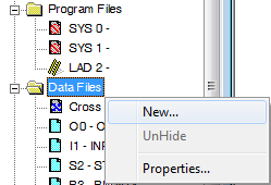
I’m going to set up a few data files that we will use for trapping. We could do this all in a single data file. However, I will create multiple data files, so we can more easily keep track of our files that are used. You can use this document an example for Trapping in the SLC-500, or in the PLC-5. Remember, the numbering system for the I/O on the PLC-5 is in octal. Right-click “Data Files”, and choose “New”.
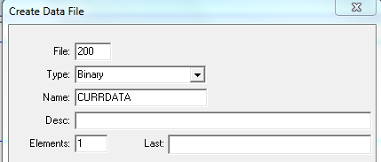
I will number this file 200 because it is not in use. The type is Binary. I named it CURRDATA, and need only one element.
I created the data table files as follows:
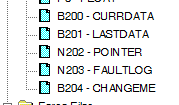
- File 200 is a Binary type named CURRDATA with 1 element.
- Data File 201 is a Binary type named LastData with 1 element.
- File 202 is an Integer file named Pointer with 1 element.
- Data File 203 is an Integer file named FAULTLOG with 50 elements.
- File 204 is a BINARY file named CHANGEME with 1 element.
When finished, the data files should appear as follows:
Description of Data files
- File 204 is simply a place holder. These addresses will later be changed to the bits we wish to track.
- Data File B200 will hold the data from the current scan of the bits we wish to track. B200 will match our field devices.
- File B201 will contain the last data that we logged.
- Data File N202 will be used to change the location of the FaultLog that we write to. We will use indirect addressing for this. For example: The first time our data changes, we log to N203:0. We don’t want to overwrite this change the next time we have a fault. The next data change will be logged to N203:1, and so on.
- File N203 will keep a lot of each time our data has changed (up to 50 instances in this case).
Write the initial logic
Next, we will add 16 lines of logic that will load the “ChangeMe” bits into the current data. Later on, the “ChangeMe” bits will be changed to the bits in logic that you wish to track. Remember, we are simply creating a tool for later use.
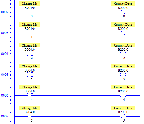
The first line of logic will look like this:
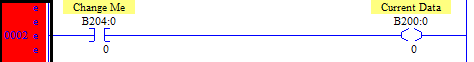
Now, copy and paste this rung 15 more times. Increase the bit number for each rung. Our bits will be numbered 0 through 15. Be sure to change the bit numbers for both the XIC and the OTE. Here is how the first few rungs will appear (you get the idea)!
Build the Fault Log logic
Next, we need to detect if there is a change in the current data. If the status of the devices we want to monitor has changed, we need to put the new data into the log file. After this, we need to increment our pointer. We also need to write N200:0 to N201:0. Remember N201:0 will display the last data we logged. Every time we log data, we update N201:0.
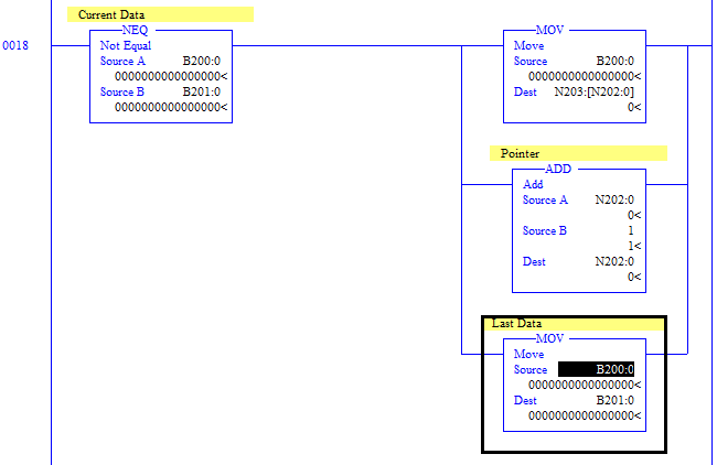
Notice the first MOV statement. The destination of this instruction uses an indirect address. N202:0 is our pointer. With indirect addressing, just substitute the address for the value of the address. For example: N202:0 = 0. Therefore, the current data will be logged to N203:0. The next instruction adds 1 to N202:0. Therefore the next time the first MOV instruction executes, the current data is stored to N203:1, and so on.
Finally, we have one more rung to write! The length of our faultlog is 50 elements. If we try to write to an address that does not exist, the processor will fault.
At last, here is the final rung!
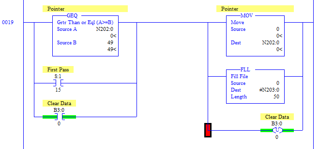
This rung will not allow the pointer (N202:) to exceed 49. If it does, the pointer will move back to the top of the fault log, and we fill the fault log with the value of 0.
Secondly, when the processor is booted, S:1:15 goes true for one scan, and will also reset the faultlog.
Lastly, we can toggle a bit (manually in RSLogix) to reset the fault log. With this logic, you only need to toggle the internal bit (B3:0/0) one time, then it will unlatch itself.
Using the Fault Log
Remember, to use this too, you must change the first 16 rungs we entered. Simply change the B204 bits to the bits in logic you wish to monitor.A, we now see the data that is logged!
At last, we now see the data that is logged!
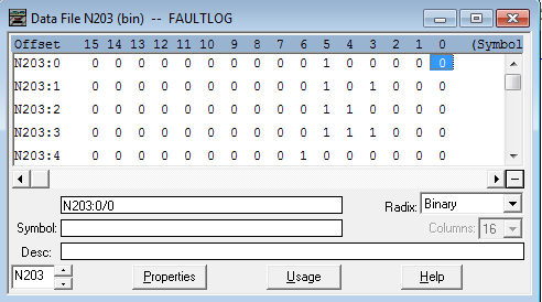
Compare the last entry to the entry above it. That will show you the last bits that have changed. To know for sure what the last entry was, just subtract 1 from N202:0. You are now trapping in the SLC-500!
To view more information on the SLC-500, visit the Category Page!
— Ricky Bryce