
Introduction to SLC-500 Basic Instructions
When you are new to programming, there are 3 SLC-500 Basic Instructions that are a good place to start. In this document, we will discuss the operation of each of these instructions in ladder logic. These instructions include:
- XIC (Examine if Closed) — or “Examine ON”
- XIO (Examine if Open) — or “Examine OFF”
- OTE (Output to Energize)
The XIC Instruction

First of all, I’ll discuss the XIC instruction. Undoubtedly, this is one of the most common instructions in ladder logic. In general, the XIC can look at most any bit anywhere in memory. As long as that bit has the value of 1, the instruction is true. However, when the bit we examine has the value of zero, the instruction is false. As an illustration, I’ll place the value of 1 into B3:0/0. Notice the instruction “Intensifies” indicating the instruction is true. An example of where you might see an XIC would be on a start switch for a motor. The XIC would go true when the operator energizes the start switch.
The XIO Instruction
The XIO instruction is used in logic for conditions that we need to evaluate as false. Similarly, the XIO instruction can generally look at any bit anywhere in memory. If that bit is a 0, the instruction is true. When the bit contains the value of 1, the instruction is false. An example of usage would be for alarms. When the operator presses a button to start a motor, we can check to make sure no alarm conditions exist before the motor will start. When the instruction is intensified (such as shown), the instruction has logical continuity. Think of this as a “NOT” instruction. In this case, B3:0/2 has to NOT be on. It must contain the value of 0 for the instruction to be true.

Output to Energize
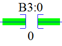
The Output to Energize instruction controls the bit we wish to manipulate based on the conditions of the rung. For example: The OTE can write the value of 1 or 0 to an output table to control a motor. This will be based on the conditions before the rung. Below is an example of how the OTE instruction appears in logic:

Putting it all together
Consider the following rung as an example:
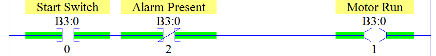
In this example, B3:0/0 represents the state of a start switch. B3:0/2 represents an alarm condition, and B3:0/1 controls a motor. In order for the motor to run, the start switch must be on, and we need for the alarm to be clear (value of 0), then the motor will start.
For more information on the SLC-500, check out the Category Page!
For a full list of SLC-500 instructions, go to the Instruction Set Reference Manual.
— Ricky Bryce