
Introduction to PlantPAx 4 Analog Inputs
In this section, we’ll discuss PlantPAx 4 Analog Inputs. There are three instructions that we will set up. The first instruction will be the channel (P_AIChan). Secondly, we’ll discuss the Analog Input (P_AIn) instruction. Optionally, you can to import the Module Status (L_ModuleSts) to get diagnostic information from the module. The channel instruction will be for conditioning the raw data, and detecting problems with the Analog Input channel. Our second instruction will scale the data, and provide an operator interface to configure both the channel, and the scaling. You can use the L_ModuleSts instruction to check for problems with the module in conjunction with the P_AInChan instruction. In this case, since this module is on analog, we’ll just read a module fault from the adapter. This is an example only, and the actual application at your facility may differ.
Import the Instructions
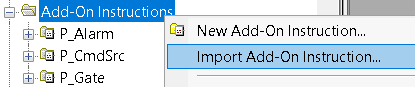
At this time, we need to import the instructions that we need for the Analog Inputs. Right-click the “Add On Instructions” folder, and import an instruction. We will be offline to perform the import.
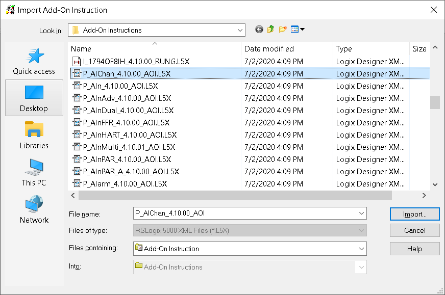
Be sure to choose “P_AIChan” as our instruction to import.
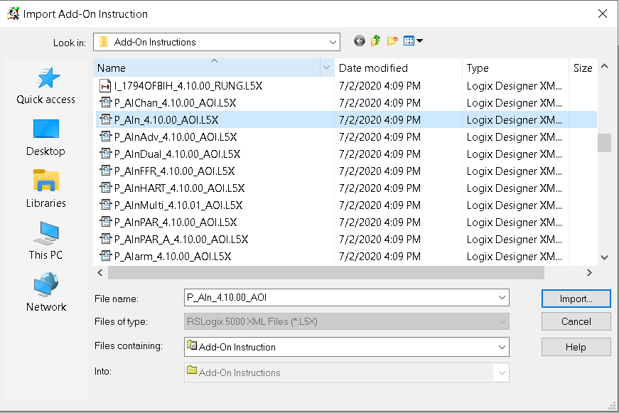
In like manner, import the P_Ain instruction.
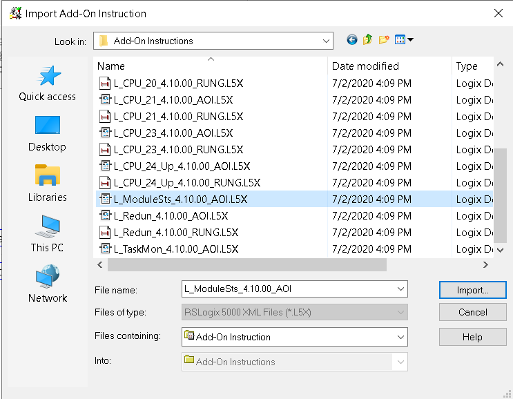
In the same way, you might import the L_ModuleSts instruction. You will find this in the Logix Diagnostics folder.
Add the Logic
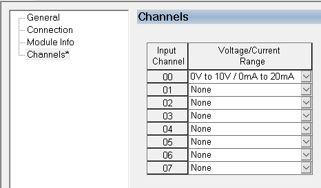
Before we start, make sure the module is configured properly. Go to the properties of the analog module in your I/O configuration tree. In the “Channels” or “Configuration” tab, be sure to configure each channel for the proper voltage or current for the field device that you have connected to that channel. In this case, our analog module is in the flex chassis in slot 2. I have a potentiometer wired to channel 0, which will provide 0 to 10 volts.
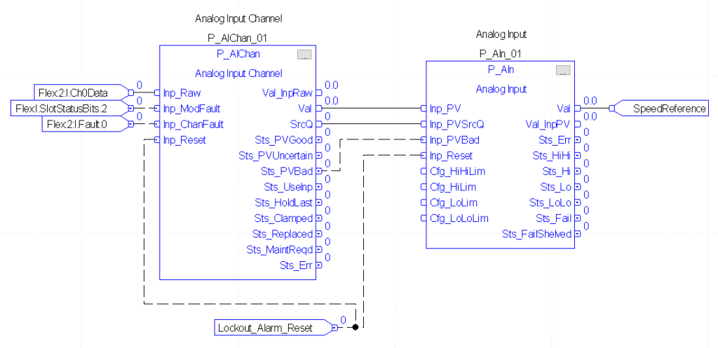
At this time, we’ll add the following logic to an existing function block routine. Keep in mind that if you create a new subroutine, you must use the JSR instruction to execute that subroutine. The tag “SpeedReference” is where we will store the result of the scaled value. We’ll create this tag with a DINT data type.
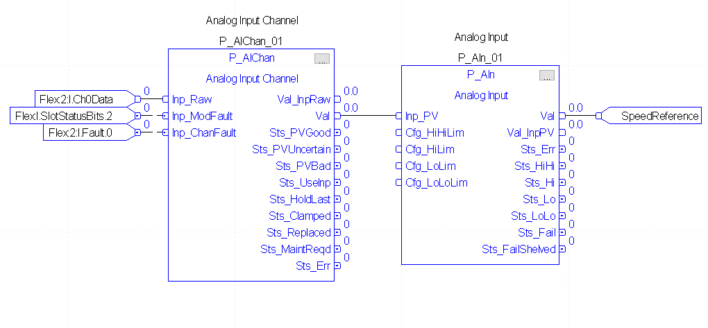
Next, we’ll make some adjustments so we can reset the instructions from a push button on the HMI. We’ll also let the P_Ain instruction know if the process variable is bad, as well as the quality.
Configure the instructions
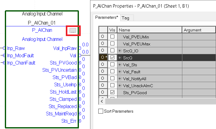
Go into the configuration of the P_AIChan instruction by clicking the ellipsis (three dots) in the upper left corner of the instruction. Then we’ll check the visibility field for “Inp_Reset” (not shown in image below), and “SrcQ”. This allows us to feed the Source Quality to the P_Ain instruction.
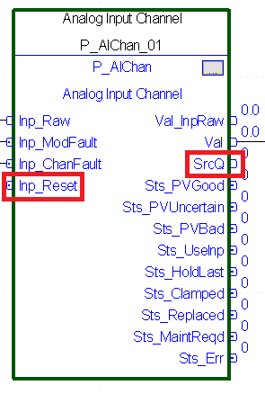
Notice that we now have the ability to connect to the Inp_Reset, and SrcQ.
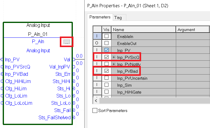
Likewise, click the ellipsis on the P_Ain instruction. Let’s check InpPV_SrcQ, and InpPV_Bad. This allows us to connect the quality and state of the PV from the P_AIChan instruction. Also check Inp_Reset (Not shown).
Finally, we will finish the logic. Don’t forget to create a tag called “Lockout_Alarm_Reset” as BOOL. This allows the operator to reset this instruction (as well as others) from a single push button on the HMI.
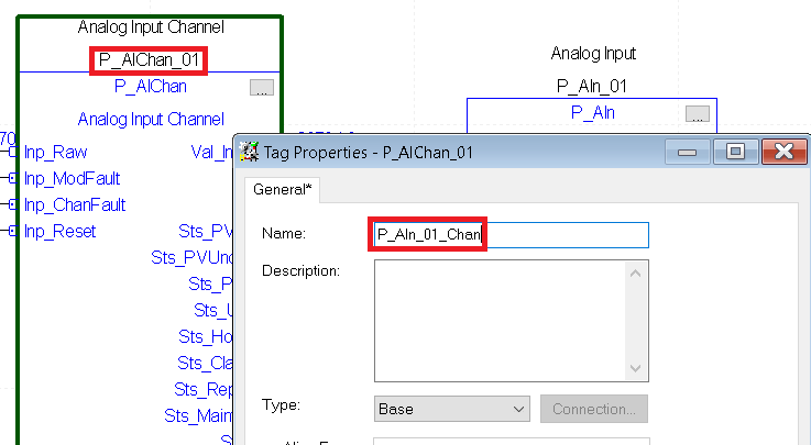
At this point, we only need to rename the tag for the P_AIChan instruction so the HMI can locate it. Right click the tag name of the Analog Input Channel instruction, and “Edit” the properties of the tag. The tag must be the same as the P_Ain instruction, then add “_Chan” to the end of the tag name. Hit OK.
Download your project to the processor, and go to run mode.
Add the Faceplates
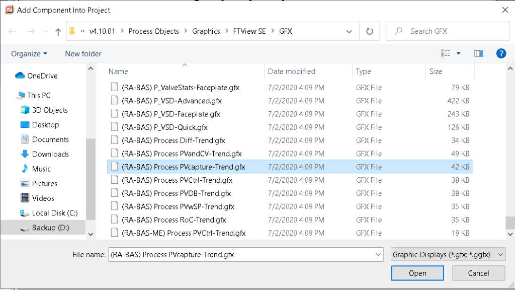
At this time, we are ready to add the faceplates. Go back into FactoryTalk View, and right click “Displays” under “Graphics. Choose to “Import Component into Application”. Hold down CTRL, and select the following graphics (GFX) objects:
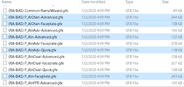
Let’s also import the Process PVCapture-Trend.
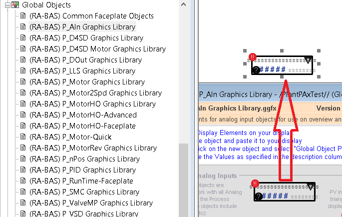
At last, we’ll create a new display, and drag the Analog Input global object onto our display.
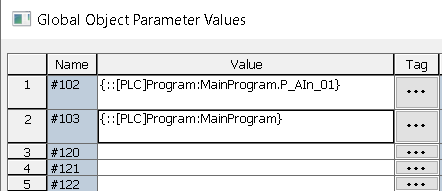
At this time, right click the object on your display, and choose “Global Object Parameter Values”. Find your tag for the P_Ain instruction. Be sure to set parameter #103 also as the path. This will be the folder that your tag was located in for the P_Ain instruction.
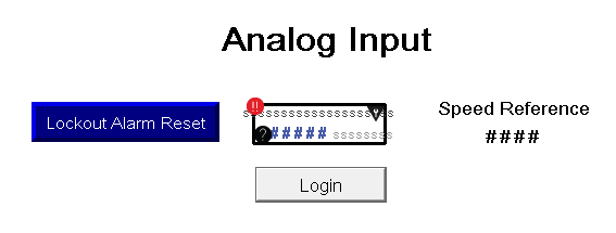
As I have said, we need to also add a momentary pushbutton object. This object will write to the “Lockout_Alarm_Reset” tag. We’ll also add a numeric display object that will display our “SpeedReference” tag. This will just confirm that the tag is equal to what our Analog Input object is showing us.
You are ready to launch the client. Be sure you have a way to get to this analog display screen. For this purpose, we’ll just make “Analog” the initial display when we create the client configuration file.
Configure the Parameters
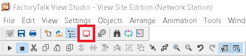
Now that we finally have the display running, we will configure the parameters of the object for our PlantPAx 4.1 Analog Inputs. Log in, then click the analog input object on your display screen.
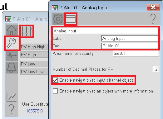
We’ll go to Maintenance, Display Advanced Properties, and on the HMI Configuration tab, set your description, label, and tag. Be sure to check “Enable Navigation to Input Channel Object”.
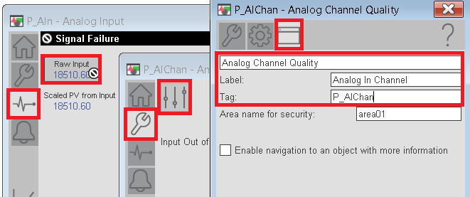
Next, we’ll bring up the Channel Faceplate to configure it’s Label, Tag, and Description. To get to this display, go to Diagnostics, Raw Input. This brings up the Channel’s faceplate. Then, go to Maintenance, Advanced display properties, and then to HMI Configuration.
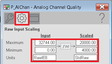
To convert the devices raw data to a company standard raw data, go go the “Engineering” Tab. In this case, the 1794-IE8 module gives us raw data values of 0 to 32744. Some companies have standards that expect the raw data to be 4000 to 20000. Later on, we’ll scale the standard raw value to engineering units.
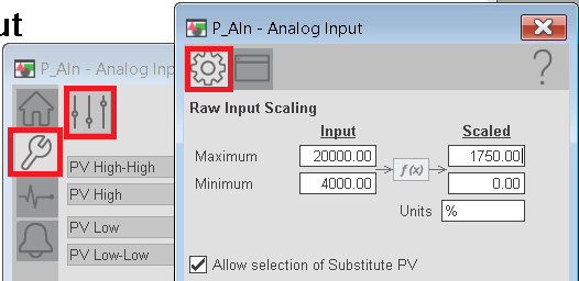
Next we’ll go back to Maintenance on the P_Ain faceplate, then display advanced properties. We’ll set the scaling as follows. This will use the 4000 to 20000 raw input, and scale this to 0 to 1750 RPM (Assuming this is a speed reference for a motor).
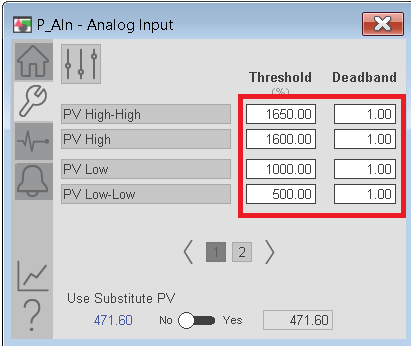
On the “Maintenance Tab”, set the alarms as follows:
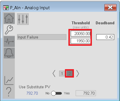
On the second page, we’ll set the failure thresholds.
We now have the project configured well enough to get valid scaled data, and alarming conditions!
For information on other instructions, visit the PlantPAx Category page.
— Ricky Bryce