
Introduction to ControlLogix Producer Consumer Model
The ControlLogix Producer Consumer model is a way for processors to share information. This can be an array of DINTs, or it might be a user-defined datatype designed to contain the status of equipment.
An example of where we might use the Producer Consumer model would be on a conveyor system. If part of the system stopped working, then other processors would need to know that there is a problem on the system. This would prevent a pileup on the conveyor.
The processor producing a tag is publishing the data in the tag for other processors to receive. The processor Consuming data is receiving data from a produced tag in another processor.
Producer/Consumer has several advantages over the MSG instruction in logic. Producer/Consumer happens at the tag level, so no logic needs to be executed for producer/consumer to transfer data. Since it happens at the tag level, even if the processor is in program mode, the data will still transfer. Another advantage is that producer/consumer can be multicast. This means that if 5 processors are consuming data, the tag only needs to be transmitted on the network one time for all consumers to receive the data. Producer/Consumer is also scheduled. We can schedule an update time of up to 750ms. The MSG instruction was dependent on the scan of the processor.
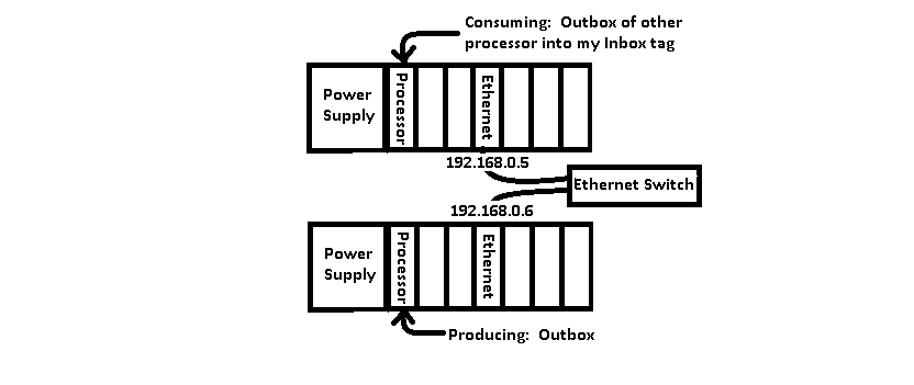
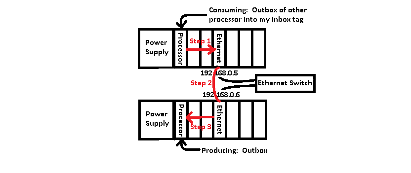
Here is an image of what we will be doing. Through the rest of this documentation, please refer to this diagram:
Configuring the Produced tag
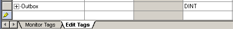
Setting up the produced tag is very easy. Open the project of the processor that will be producing data. All we need to do is make a tag and mark it as produced. Go to the controller tag database, and in “Edit Tags”, we’ll create a tag called “Outbox”. Let’s just keep this simple, and leave it as a DINT.
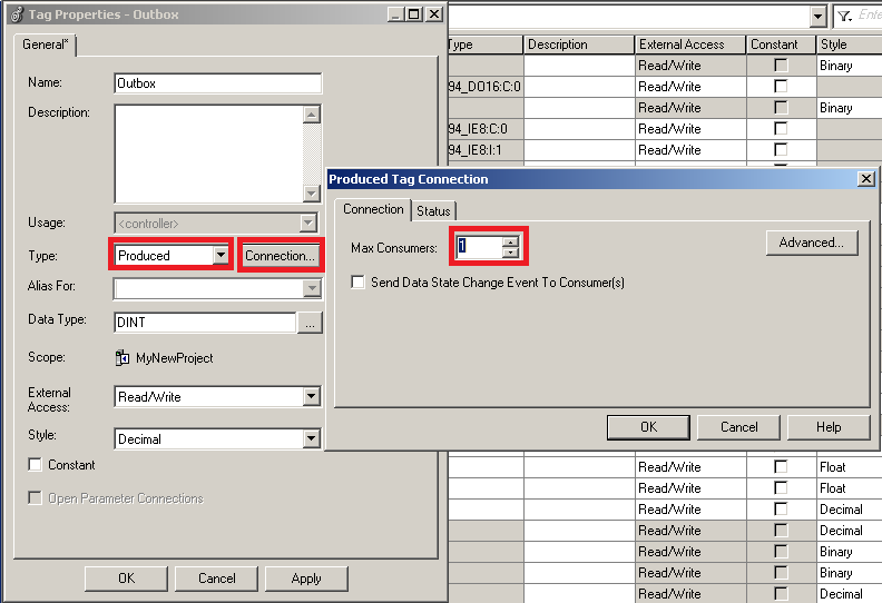
Now, Let’s right-click the tag, and choose “Edit Outbox Properties” We need to change the type of tag to “Consumed” then click the “Connection” button. You will see that we are producing this tag for up to 1 consumers, which is fine for what we are doing in this example.
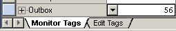
Next, let’s go to “Monitor Tags”, and for now, we’ll place a random value into the Outbox tag. In a real application, you would be moving data into the tag such as equipment speed setpoint, or bits that indicate the status of this processor.
If you are offline, please download to your processor that will produce the data.
Configuring the Consumed Tag
Next, go to the project of the processor that will be consuming data. This processor has a little more work to do. First, we must build our path to the target processor. The target processor is the processor that is producing the data. (outbox) After we build the path to our target processor, then we can create our consumed tag.
Look at the first diagram in this post. There are 3 steps to building the path:
1. First, we will connect to our own Ethernet module.
2. Second, we will connect from OUR Ethernet Module to the Ethernet module in the target chassis.
3. Last, we connect to the processor on the remote chassis backplane.
Before we start, you will need to know the slot numbers, firmware revisions, and IP addresses of all the modules involved here. If you don’t have that information, just open your web browser, and enter the IP of each Ethernet Module, and click “Browse Chassis”. This will display the slot, catalog #, and revisions of each module. Also be sure you are in the project of the processor that will be consuming data from the producer.
Build the path
Step 1
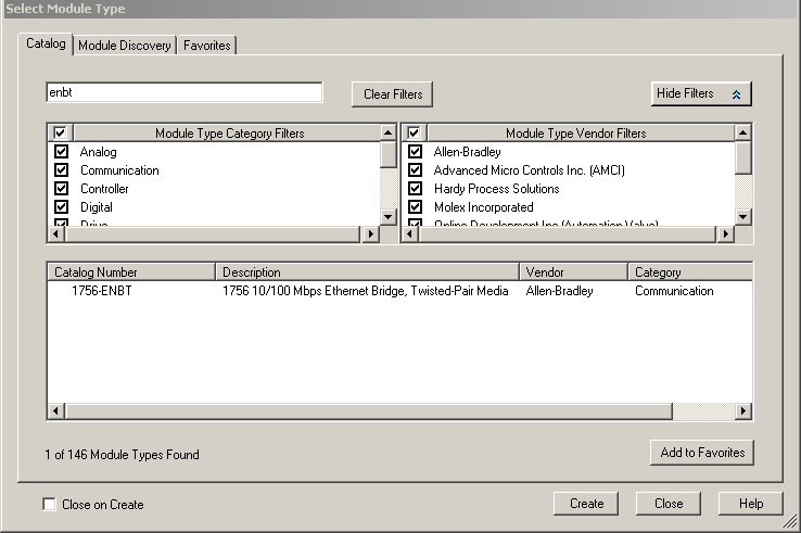
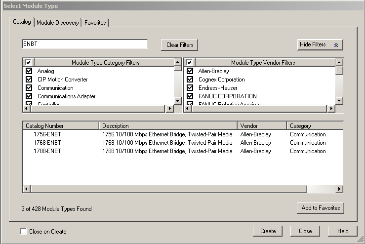
In Step 1, we need to add our Ethernet module to the backplane (If it is not already there). If you already have an existing Ethernet module in your project, then this step is already complete. Here, we will add a 1756-ENBT module. Be sure to adapt this example to the module that you are using (ie. EN2T, or 1756-CNB).
Right-Click the backplane, and add a new module to your own backplane.
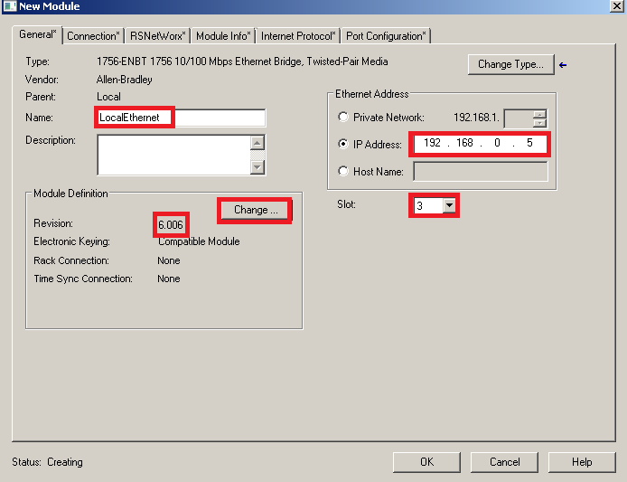
Be sure to set up the properties according to the module that you have.
Step 2
Now that we have our own module defined, we need to add the target module. Right click the Ethernet Network below the module we just added to add a new module.
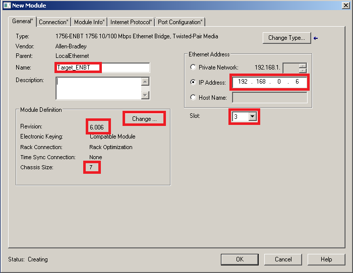
We will be adding the network adapter in the target chassis.
Be sure to populate ALL fields properly. The most common mistake on this step is forgetting to change the chassis size of the target chassis.
Step 3
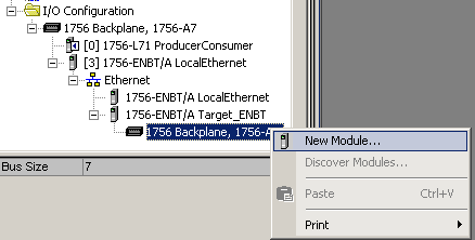
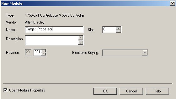
Next, Right-click the backplane of the TARGET chassis to add the target processor. Remember, this is not our own chassis. We will be adding the processor that is producing the data to it’s own chassis.
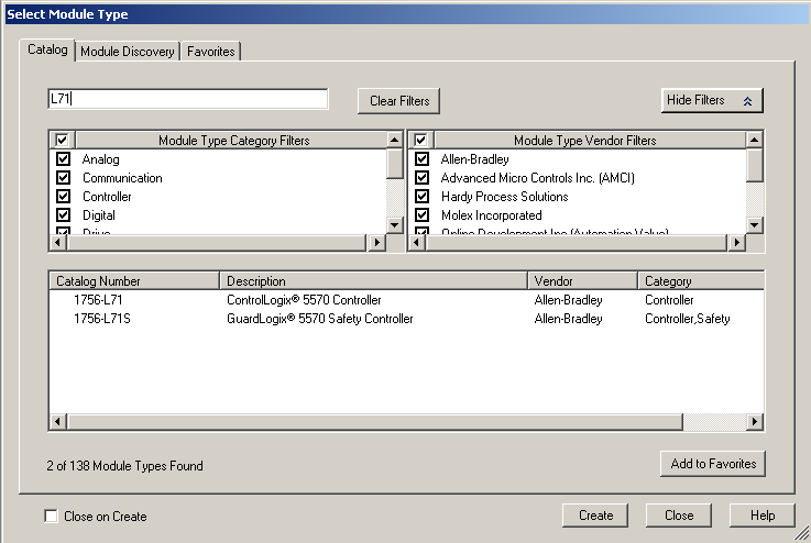
In our example, we are adding an L71 processor to the backplane. Be sure to modify this step for the model number of your own processor.
Be sure to populate all fields correctly.
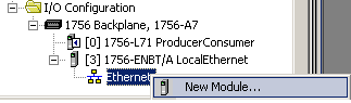
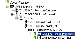
When you are finished, your I/O Tree should look similar to this:
Create the Consumed tag for th ControlLogix Producer Consumer Model
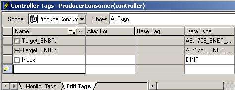
Now, let’s go to the controller tag database. Furthermore, we need to be in “Edit Tags” mode. We will create a tag called “Inbox”. This datatype must match the datatype of the tag that is producing the data. The “Outbox” tag in the target processor has a DINT Datatype.
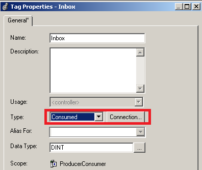
At this point, right-click the tag “Inbox”, and choose “Edit Inbox Properties”. We will make this a consumed tag.
Click the “Connection” Button, and we will configure this tag to connect to the Outbox tag of the target processor
Obviously, the producer is “Target_Processor”, because that is what we named the processor in the I/O Tree. Be sure to populate the “Remote Data” Field. This will be the tag in the Target_Processor that we want to consume data from.
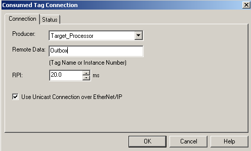
The RPI is the “Requested Packet Interval”. The lower this number is set, the faster the tag will update. If this number is set higher, the tag will update less frequently, but we are reducing the amount of traffic on the network.
At this point, Download to your processor, and go to “Monitor Tags”. Your “Inbox tag should match the random data that we placed into the Outbox of the producing processor.
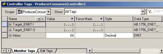
If you are still online with the processor that is producing the Outbox, change the value in the Outbox. You will see the value change within 20ms on the consumed tag.
Summary for the ControlLogix Producer Consumer Model
In short, the ControlLogix Producer Consumer Model is one way for processors to transfer data between each other. In the processor that is producing the data, you simply create a tag and mark this as produced. On the other hand, the processor consuming the data has a few more steps. First, you must have a path to the target processor. At this point, you create a tag, then make this tag consumed. Next, in the properties of the tag consuming data, you must tell the tag what processor to consume data from. Additionally, you must tell the consumed tag which tag in the producer to receive data from.
Just be sure you configure the produced tag for the number of consumers to expect. The advantage of using this model is that the data transfer is deterministic. That is to say, it has a regular update interval. Additionally, the producer consumer model can be multicast. If you are doing this over Ethernet, then you must have a 1756-ENBT or later. (The old 1756-ENET will not work). If you are doing this over ControlNet, then you must re-schedule the network once your producer consumer model is set up.
For more information about ControlLogix, please visit the ControlLogix Post page!
— Ricky Bryce