
Introduction to SLC-500 Remote I/O (1747-SN)
There are many reasons to use SLC-500 Remote I/O (1747-SN). Imagine a conveyor system. Ten thousand feet from the local processor chassis, you have 256 points of I/O. With Remote I/O, you could mount a chassis up to 10,000 feet from the local processor with a Remote I/O adapter, and the processor could control the I/O directly. This would eliminate the need to run 256 cables from the remote location all the way back to the processor.
We also use Remote I/O to increase the number of I/O points the processor controls. Sometimes the amount of I/O we need wouldn’t normally fit in a standard SLC chassis, or even extended local I/O on the SLC.
A key concept to understand is that the 1747-SN (Scanner Module) converts PLC-5 typed addressing into SLC addressing. (Racks and Groups into Slots and Words)
Consider the Following Image:
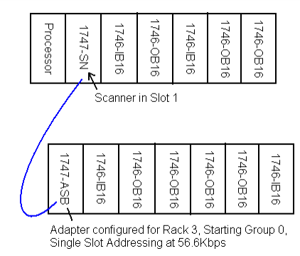
SLC-500 Remote I/O (1747-SN) Terms
Memory
Bit
This is the smallest unit of information the processor can handle. A bit can only have 2 states: On or Off, True or False, 1 or 0, Yes or No (however you wish to express it)
Word
In the PLC-5 and SLC, a word is a memory location consisting of 16 bits by definition. The entire input and output data tables are made up of 16 bit words. You can see this clearly when the RADIX is switched to BINARY.
Group
The Group is a PLC-5 Term. A Group is a memory location consisting of one word of input, and one word of output. (An input/output pair).
Rack
The rack is another PLC-5 term. A Rack is a memory location consisting of 8 Groups. Important: A RACK ALWAYS consists of 8 Groups. The Rack is not the same as a chassis on Remote I/O. A chassis can be small enough that it does not take up an entire rack of memory, or may be large enough that it consumes more than one rack of memory. Please do not get the terms Rack and Chassis confused.
Other Terms
Addressing Mode
Switches located on bank #3 on the SLC adapter, or the backplane of a PLC-5 chassis determine the addressing mode. In 1-slot addressing, an entire group is dedicated to each slot. In 2-slot addressing, a group is dedicated to every 2 slots. In ½-slot addressing (less common), a group is dedicated to every ½ slot (This means you get 2 groups for each slot).
Baud Rate
The baud rate is the speed at which communication takes place on the network. All devices on the same network MUST run at the same baud rate. With a baud rate set set 57.6K, communication is possible for network distances up to 10,000 feet. As the baud rate increases, the allowed network distance shortens. For a baud rate of 115.2K, your network is limited to 5000 feet, and for a baud rate setting of 230.4K, the maximum network distance allowed is 2500 feet.
Terminators
BOTH ENDS of the network must be terminated to hold the network impedance at the proper value. The value of the resistor depends on the baud rate. For baud rates of 57.6K and 115.2K, you will terminate both ends with a 150 Ohm resistor. For 230.4K, use an 82 Ohm resistor. The resistor should be ½ Watt (non-inductive) with a 1% tolerance.
(Note: For extended node capability (Not as common), you will always use an 82 Ohm resistor)
SLC-500 Remote I/O (1747-SN) Physical Topology
There are no restrictions on the space between devices on the network as long as the total network length does not exceed the specification for the chart below (with no extended node capability)
| Baud Rate | Maximum Network Distance | Value of Terminating Resistor |
|---|---|---|
| 57.6 Kbps | 10,000 ‘ | 150 Ohm |
| 115.2 Kbps | 5,000 ‘ | 150 Ohm |
| 230.4 Kbps | 2,500 ‘ | 82 Ohm |
Here is a typical network.
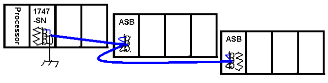
Note: When wiring the Phoenix connectors on the scanner and adapters, you should never have more than 2 wires under any 1 screw terminal. Your devices are daisy-chained together or connected in a trunkline/dropline configuration with a special connector box. Star topologies are NOT supported.
Ensure the shield is only grounded at one end. Shielding the ground a both ends could cause a ground loop.
Gathering Information:
The are 4 things you must know about any device that runs on Remote I/O.
- Rack
- Starting Group
- Baud Rate
- Size (In Racks)
If we had a chassis running on remote I/O, and our system was down, we could remove the adapter from the chassis to gather all the information we need.
Rack Number (for ASB) when used with SLC-500 Remote I/O (1747-SN)
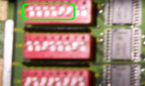
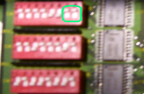
Below is a SLC adapter module, A PLC-5 Adapter module, and the PLC-5 backplane. Let’s explain how to find or set the Rack Number for each type of adapter:
The SLC adapter (top) PLC-5 Adapter (bottom): Switches Switches 1 to 6 on Switch Bank 1:
Here are a few settings for the switches
| Rack # | Switch 1 | Switch 2 | Switch 3 | Switch 4 | Switch 5 | Switch 6 |
|---|---|---|---|---|---|---|
| 0 | ON | ON | ON | ON | ON | ON |
| 1 | ON | ON | ON | ON | ON | OFF |
| 2 | ON | ON | ON | ON | OFF | ON |
| 3 | ON | ON | ON | ON | OFF | OFF |
| 4 | ON | ON | ON | OFF | ON | ON |
| 5 | ON | ON | ON | OFF | ON | OFF |
| 6 | ON | ON | ON | OFF | OFF | ON |
| 7 | ON | ON | ON | OFF | OFF | OFF |
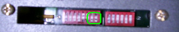
Starting Module Group (SMG)
The Starting Module Group (SMG) can be found by looking at switches 7 and 8 on Switch Bank 1 on either the SLC Adapter (top) or the PLC-5 Adapter (bottom)
Use the following table to determine the Starting Module Group:
| Starting Module Group | Switch #7 | Switch #8 |
|---|---|---|
| 0 | ON | ON |
| 2 | ON | OFF |
| 4 | OFF | ON |
| 6 | OFF | OFF |
Why have a Starting Module Group? Remember the difference between a Rack and a Chassis. A Rack is a memory location, and a chassis is the physical device that modules are placed in. A Chassis could be so small that it only consumes half a rack of memory (Groups 0 to 3), so then we could put another chassis in the same rack starting at module group 4, then it would consume groups 4-7. Below is an example of this. All 8 groups of Rack 1 are consumed by 2 chassis.
Baud Rate:
The baud rate is the speed at which communication takes place on the network. All devices on the same remote I/O network must run the same baud rate.
The baud rate switches for the PLC-5 and the SLC are in the same location on switch bank 2, but the charts are separate for determining the baud rate.
SLC Adapter (Switch Bank 2 – Switches 1 and 2):
| Baud Rate | Switch 1 | Switch 2 |
|---|---|---|
| 57.6 K | ON | ON |
| 115.2K | ON | OFF |
| 230.4K | OFF | OFF |
PLC Adapter (Switch Bank 2 – Switches 1 and 2)
| Baud Rate | Switch 1 | Switch 2 |
|---|---|---|
| 57.6K | ON | OFF |
| 115.2K | OFF | OFF |
| 230.4K | OFF | ON |
Image Size:
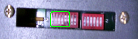
The next piece of information we need to gather is the image size. This can be done by looking at the backplane switch on the PLC-5 Adapter’s chassis, or Switch #3 on the SLC Adapter. (Note: Since there are no backplane switches on the SLC, switch bank 3 was necessary on the SLC adapter to handle the functions of the backplane switch on the PLC-5 chassis)
Once we determine the addressing mode, we can figure out what size the chassis is. Let’s find what addressing mode your chassis is configured for, then we’ll figure out the size.
Look at Switch Bank 3 on the SLC Adapter, or the Backplane switches on the PLC-5. (Switches 5 and 6)
| Addressing Mode | Switch 5 | Switch 6 |
|---|---|---|
| 2- Slot | OFF | OFF |
| 1-Slot | ON | OFF |
| ½ Slot | OFF | ON |
Deriving the Size:
Remember the definition of Addressing Mode:
Switches located on bank #3 on the SLC adapter, or the backplane of a PLC-5 chassis determine the addressing mode. In 1-slot addressing, an entire group is dedicated to each slot. In 2-slot addressing, a group is dedicated to every 2 slots. In ½-slot addressing (less common), a group is dedicated to every ½ slot (This means you get 2 groups for each slot).
Let’s look at some examples – You will notice the adapter is not counted as an I/O group:
1- Slot Addressing – Each group is dedicated to a slot (each chassis below consumes ½ Rack)
2-Slot Addressing – Each group is dedicated to every 2 slots (each chassis below consumes ¼ Rack)
½- Slot Addressing – Each group is dedicated to every ½ slot. (2 groups per slot) Each chassis below consumes an entire rack of memory. This mode is generally used with 32 point modules.
Sizing Chart
You can use the chart below as a cross reference to derive the size if you know how many slots are in the chassis, and the addressing mode.
| PLC-5 Chassis Size | 2-Slot Addressing | 1-Slot Addressing | ½ Slot Addressing |
|---|---|---|---|
| 4-Slots | ¼ Rack | ½ Rack | FULL (1 Rack) |
| 8-Slots | ½ Rack | FULL (1 Rack) | 2 Racks |
| 12-Slots | ¾ Rack | 1 ½ Racks | 3 Racks |
| 16 Slots | FULL (1 Rack) | 2 Racks | 4 Racks |
The SLC chassis do not generally come out to even numbers, but are generally set according to the guidelines. For example: If you have an SLC chassis in 1 slot addressing, the adapter would go in the first slot of the chassis. If there were six other slots left in the chassis, we would say the chassis consumes ¾ or a rack. Because the SLC chassis do not always come out even, an additional switches are used on the SLC chassis to manually assign the size. This size setting is located on Switch Bank 2, switches 5-8.
SLC Size Settings for the 1747-ASB (SLC only)
The next page will explain each setting configuration. This step is NOT required for a PLC-5 chassis. The adapter automatically recognizes the size in the PLC-5.
| Image Size (In Groups) | Switch 5 | Switch 6 | Switch 7 | Switch 8 |
|---|---|---|---|---|
| 2 | ON | ON | ON | ON |
| 4 | ON | ON | ON | OFF |
| 6 | ON | ON | OFF | ON |
| 8 | ON | ON | OFF | OFF |
| 10 | ON | OFF | ON | ON |
| 12 | ON | OFF | ON | OFF |
| 14 | ON | OFF | OFF | ON |
| 16 | ON | OFF | OFF | OFF |
| 18 | OFF | ON | ON | ON |
| 20 | OFF | ON | ON | OFF |
| 22 | OFF | ON | OFF | ON |
| 24 | OFF | ON | OFF | OFF |
| 26 | OFF | OFF | ON | ON |
| 28 | OFF | OFF | ON | OFF |
| 30 | OFF | OFF | OFF | ON |
| 32 | OFF | OFF | OFF | OFF |
Making it work!
Your lawnmower will generally run if you have 2 things: Gas and Spark.
The SLC adapter will generally run if you do 2 things: Check or Set the Adapter Parameters, and Tell the scanner to scan the adapter. (Your cabling system must also be in tact)
For our classroom system, write down the parameters you found on the adapter you will be scanning:
Rack ___________
SMG ___________
Baud Rate _______
Size ____________
Set up the Project for SLC-500 Remote I/O (1747-SN)
Now we need to tell the scanner to scan the adapter. We’ll do that in the I/O Configuration in RSLogix 500. Be sure the 1747-SN module is in the I/O Configuration. If not, Just drag the scanner module from the list of Available modules, and drop it into the appropriate slot.
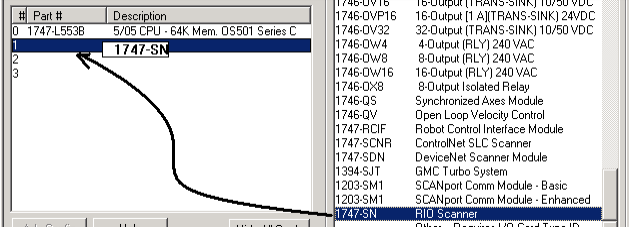
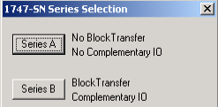
The series of the scanner is printed on the side of the module, so be sure to select the appropriate series.
Double click the scanner module in the I/O Configuration, or highlight the scanner, and click “Advanced Configuration”.
Choose “Edit ‘G’ Data” This is the scanner confiGuration data.
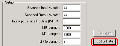
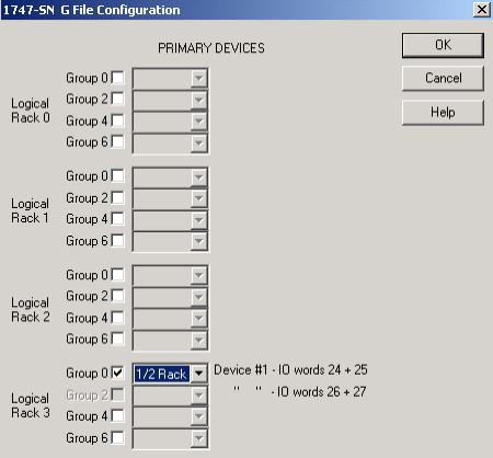
Next, set up the scanner to scan your adapter(s). In this example, I’m going to scan Rack 3, SMG 0, ¼ Rack. Be aware that the DIP switches on the Scanner module itself must be set up for the same Baud Rate as the adapter, or vice-versa.
You are ready to download and test your work. Make sure the Comms light is solid green on the scanner, and that the adapter is active.
Interpreting the Data for SLC-500 Remote I/O (1747-SN)
We stated earlier that the SLC does not understand the racks and groups that all remote I/O addressing uses. These Racks and Groups must be “translated” to slots and words.
In this example, we only have one slot to work with for all Remote I/O. That is slot 1. Any device that is wired to the scanner will show up on a word in slot 1.
Let’s look at the input data table. (Note: The output table will be very similar for slot 1).
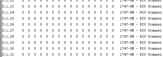
You will notice that by scrolling down, there are 32 words total for slot 1 (0 to 31). The output table is the same.
Lets do the math:
- Remember that a Group is 1 word of input AND on word of output (an input / output pair).
- In slot 1, we have 32 words of input AND 32 words of output.
- Therefore, we have 32 Groups in slot 1
- We know there are 8 groups in a Rack
- Therefore we have 4 Racks available in slot 1 (32/8)
These 4 racks are going to be numbered 0 to 3 – Let’s visually look and see how these 32 words are broken down into racks.
Addressing Chart
| Rack # | Group # | SLC Address (E = Slot # of Scanner T = type (I or O)) |
|---|---|---|
| 0 | 0 | T : E . 0 |
| 0 | 1 | T : E . 1 |
| 0 | 2 | T : E . 2 |
| 0 | 3 | T : E . 3 |
| 0 | 4 | T : E . 4 |
| 0 | 5 | T : E . 5 |
| 0 | 6 | T : E . 6 |
| 0 | 7 | T : E . 7 |
| 1 | 0 | T : E . 8 |
| 1 | 1 | T : E . 9 |
| 1 | 2 | T : E . 10 |
| 1 | 3 | T : E . 11 |
| 1 | 4 | T : E . 12 |
| 1 | 5 | T : E . 13 |
| 1 | 6 | T : E . 14 |
| 1 | 7 | T : E . 15 |
| 2 | 0 | T : E . 16 |
| 2 | 1 | T : E . 17 |
| 2 | 2 | T : E . 18 |
| 2 | 3 | T : E . 19 |
| 2 | 4 | T : E . 20 |
| 2 | 5 | T : E . 21 |
| 2 | 6 | T : E . 22 |
| 2 | 7 | T : E . 23 |
| 3 | 0 | T : E . 24 |
| 3 | 1 | T : E . 25 |
| 3 | 2 | T : E . 26 |
| 3 | 3 | T : E . 27 |
| 3 | 4 | T : E . 28 |
| 3 | 5 | T : E . 29 |
| 3 | 6 | T : E . 30 |
| 3 | 7 | T : E . 31 |
Addressing for SLC-500 Remote I/O (1747-SN)
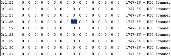
Use the chart for addressing. What address would the following light show up on in the data table if it is wired to terminal 7?
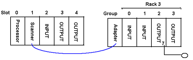
You should have figured out the address is O : 1 . 26 / 7
Let’s see this bit in the Data Table:
For more information on your particular scanner or adapter, visit AB’s Web Page.
If you are interested in more SLC-500 documents, visit the Category Page!
— Ricky Bryce
Nice Article. Thank you!. Can you do a similar analysis for when you use Analog Outputs (1794 – OF41) ??
I have seen how the mapping is different as they should be mapped to the M0 registers instead of the regular O:X.Y type of addressing and then use intermediate N registers to monitor them..
Thank you!!!
Thanks, Leonardo. Typically in the SLC, you need to use “block transfers” with analog on remote I/O. The latest firmware of the enhanced SLC’s support block transfer instructions, but with the older firmware, you had to do “virtual” block transfers for analog. Remember that Remote I/O uses the PLC-5 type addressing. In single slot addressing, you can only have one word of input and one word of output per slot… (Or two words in and out per pair) on the I/O tables. Check out the user manual for an example on how to do this with the SLC. https://literature.rockwellautomation.com/idc/groups/literature/documents/um/1794-um008_-en-p.pdf
Chapter 3 has an example that should work out for you. It’s not pretty, but it should get the job done!
Take care,
Ricky