
Introduction to Alexa voice commands to PLC
In this post, we will discuss how to send Alexa voice commands to a PLC. This is a simple process, but requires several steps. I’m simply doing an experiment to allow an Alexa voice commands to turn on various inputs on a PLC module. This document is As-Is, and use at your own risk. Be sure you have knowledge of all safety factors before utilizing this document.
Basically, we will tell Alexa to turn a light on. An ESP8266 module will receive this command. In turn, this will energize an input on a TTL (Transistor-Transistor Logic) module.
I will list the hardware I used:
- An Amazon Echo Dot
- Allen Bradley ControlLogix, SLC-500, or PLC-5 with a TTL card
- ESP8266-12E Development board. (with Micro-USB cable)
- An old Cat-5 Ethernet cable (8 conductors)
- Programming cable for the PLC
Then there is some software and subscriptions you will need to free web sites.
- RSLogix 5, RSLogix 500, or RSLogix 5000 (Studio 5000) depending on your PLC system (non-free software)
- Subscribe to Sinric.com
- Install the APP for Alexa on your phone, and set up your Echo device.
- Arduino IDE (free to download)
Sinric Setup
First, go to sinric.com, and set up an account.
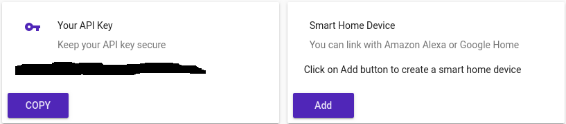
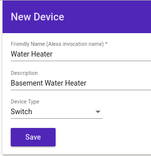
Make note of your API Key (Copy to Notepad). Next, add a Smart Home Device. (Click the ADD Button). I set up the device as follows:
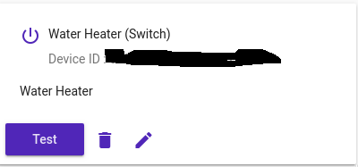
You may need to scroll down to get the Device ID of the device you just added. Paste this Device ID in your notepad also. You will need it later.
Alexa Setup
Secondly, install the Alexa app on your phone, and set up your Echo device. Use the procedure provided with your Echo. Be sure your Echo is connected to the Internet.
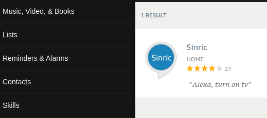
You can use your phone, or web browser to add the Sinric skill. After adding this skill, you will need to link the Sinric account. You will be guided to do this after you add the skill.
ESP8266 Setup
Be sure you have the Arduino IDE installed, and download the sinric code.
In this case, I just downloaded the ZIP file. Obviously, you need to unzip the file. I simply placed the unzipped folder into /home/arduino/libraries. Your operating system or version may vary.
Secondly, I added the ESP8266 board to the Arduino IDE. Under file | preferences, I just added this to additional board managers: http://arduino.esp8266.com/stable/package_esp8266com_index.json
You might need to close then re-open the IDE. Then I went to Tools | Boards, and selected the “Generic ESP8266 Module” option. Of course you also need to go to Tools | Port, and select the appropriate COM port for your ESP8266 (Be sure it’s plugged in!)The Code
The Code
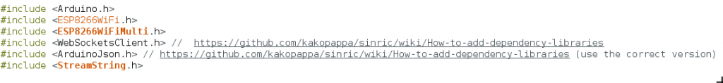
Finally, you are ready to finish the code! Be sure to install the appropriate libraries. (Follow the instructions for the links given). I’m using the switch_example file from the code downloaded from github. (We unzipped this earlier, and put it in the libraries folder.)
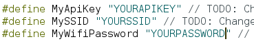
Be sure to enter the API Key from the Sinric website that you copied to notepad earlier (Replace “YOURAPIKEY”. Also enter the SSID and password of your network.
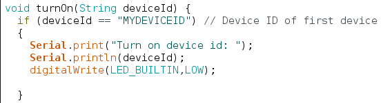
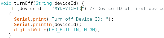
At last, set up your device! Be sure to enter the device ID for both the “TurnOn, and TurnOff” functions. For a TTL card, Low is actually the value of 1. Therefore, the TurnOn function will set the pin low, and vice-versa. Replace “MYDEVICEID” with the device ID that you copied from the Sinric site, and pasted into notepad earlier.
In the Setup Function, be sure to set the PinMode as Output. I will also set the initial state HIGH (OFF).
pinMode(LED_BUILTIN, OUTPUT);
digitalWrite(LED_BUILTIN, HIGH);
At last, upload your code to the ESP8266. Ask Alexa to discover devices. LED 2 is the Builtin LED, so you should be able to send voice commands, and see the light turn on and off. This will prove that everything is working so far. I just said “Alexa, turn on water heater”. “Alexa, turn off water heater” On my development board, the LED light is ON in the LOW state, which matches the way my TTL card will work.
PLC Wiring
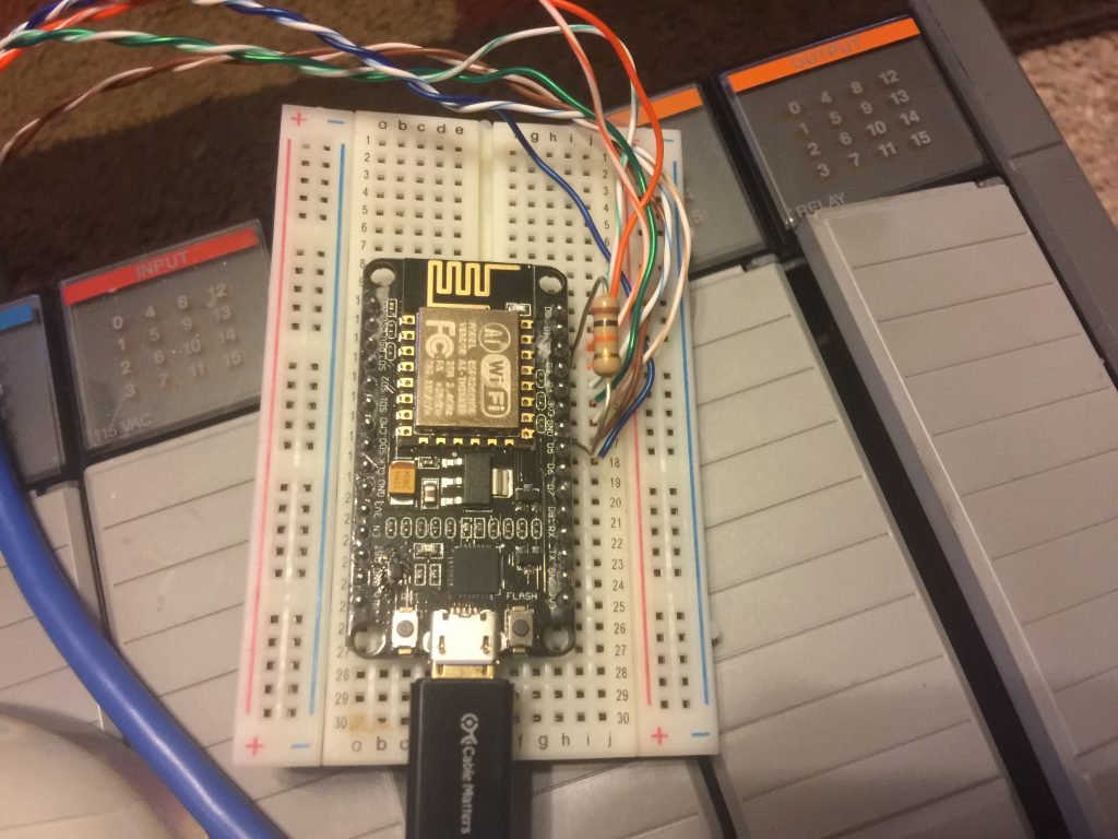
I used an old Cat-5 cable, and cut both ends off. Two of the wires will go to 3V3, and GND, respectively for power. The other six leads are connected to Digital Inputs 0 to 5.
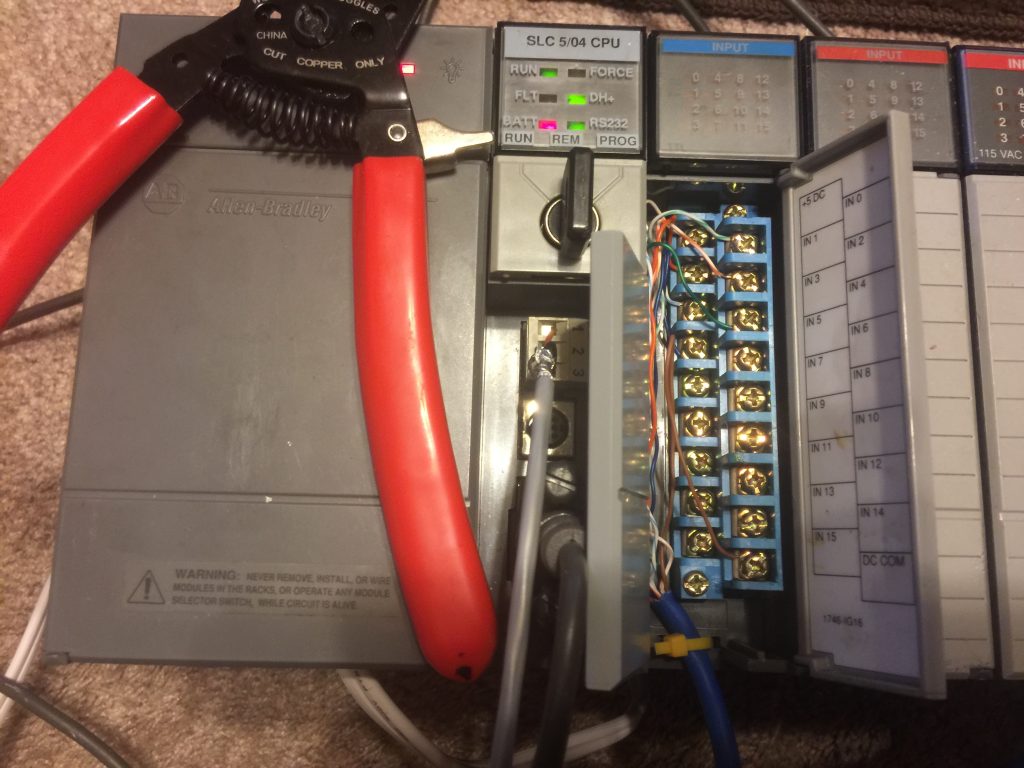
My 1746-IG16 has a sticker on the door that explains the wiring well. First I wired up the supply (5v) Even though I only had 3.3v. Secondly, I connected the GND. Be sure not to mix up the colors. They will correspond with the ESP8266 wiring. I also wired up inputs 0 to 5.
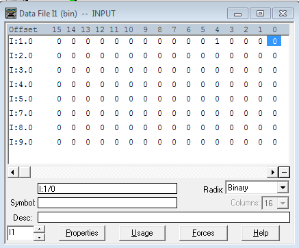
Finally, I powered everything up, and said “Alexa, turn on water heater”. The digital input status light came on, and the value of 1 was placed in the input image table (top row, bit 4) Apparently I didn’t wire them in the right order, but that is OK. Then, “Alexa turn off water heater” should set the bit to 0.
Summary
With this method, you can issue voice commands that are read by the PLC. Based on your PLC program, your options are endless! Don’t think you are just limited to the I/O of the ESP8266 or the TTL card. I’m using it in the easiest way here, but remember, you can have the ESP8266 place any bit pattern on the card to represent a numeric value of up to 32767 that can be read by the PLC. You can program the PLC to perform a different function each time this bit pattern changes.
Other Options
The above method requires a TTL module, and a lot of wiring. If your processor has a serial port, you can use the MAX232 module. This module converts serial TTL signals to RS232. Instead of placing a bit pattern on various discrete outputs, you would just send an ASCII code into your serial port. In the SLC, PLC, or ControlLogix, you would read this code with an ASCII read instruction. Your logic would then take the appropriate action based on the code generated from the ESP.
Yet another option would be to use Node-Red. Node-Red has an Ethernet/IP node available to write to the processor, and this works very well going to a ControlLogix Ethernet module. You can create “Virtual” Alexa devices in Node Red as well.
Limitations
The maximum number of “Virtual” devices I could use in the ESP8266 is 10. However, by using an ESP32, I was able to use 15 devices by default.
Feel free to write comments below or suggestions, and corrections!
If you are interested in other PLC posts, visit the SLC-500 Category Page, or the ControlLogix category page!
— Ricky Bryce