
Introduction to the Schmitt Trigger
Generally, We use the schmitt trigger to “clean up” a digital signal. When digitial data is passed through a cable, you will have capacitance. Furthermore, the longer the cable is, the more capacitance you will have. We know that capacitance opposes a change in voltage.
When transmitting data at high speeds, the voltage needs to rise and fall very quickly to transmit 1’s and 0’s across a network. When transmitting data over a long distance, this becomes very difficult. Because of the capacitance in the cable, it takes longer for the voltage to rise and fall in the cable to transmit data.
Cleaning up the signal
In this case, we have a 74HC14 Schmitt Trigger. This is an inverting trigger. That means that if I send a high voltage into the trigger, I will get a low voltage out, and vice versa.
As an illustration, let’s look at the following diagram that I made with Tinkercad.
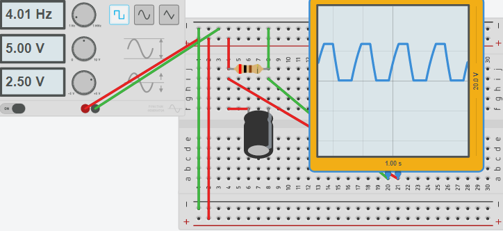
Here, we have a function generator feeding a square wave into the breadboard. I’ve used a 200 Ohm resistor to simulate a load. Remember that when you have a long cable, there will be capacitance in the cable. I’ve simulated the capacitance with a 200 MicroFarad capacitor. If you look at the output on the scope, you will see that it takes time for the signal to rise from 0 to 5 volts. Similarly, it takes time for the signal to drop to 0 volts.
Loosing signal
As the frequency increases, there is simply not enough time for the voltage to fully rise or fall, so our signal begins to degrade.
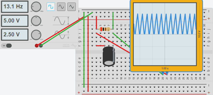
At this point, we have just threee choices. First, we can clean up the signal with a schmitt trigger. Secondly, the communication rate can be slowed down. Thirdly, we can shorten the cable (less capacitance).
In this instance, we want a high communication speed, and cannot shorten the cable, so we will clean up the signal.
Using the Schmitt Trigger
Consider the following diagram. In essense, our degraded circuit is still in place. Using the 74HC14 chip, we will clean up this signal. Once again we will have a true square wave. A stable power supply will be placed on the chip. We will feed the noisy signal into one of the chip’s inputs. Because this input is inverting, we will run the output of the first inverting input through a second inverter. The result is a pure square wave once again.
The scope on the left shows the “dirty” input. The scope on the right shows the “clean” output!
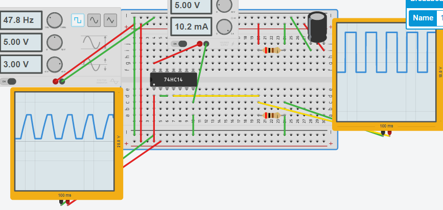
As the input to the 74HC14 rises, the output remains low until the input reaches 2/3 (66%). At this point, the output is switched fully on, and will stay on. In contrast, when the input begins to fall, and reaches 33%, the output will be low. By placing the Schmitt trigger at various points in the communication line, we can transmit high speed data for long distances.
— Ricky Bryce
How might I follow your circuit idea, by using an inductor/tank circuit as the initial input signal. Here is what I am trying to do.
The inductor or ring of multiple inductors, oscillate at a certain frequency (not sure which to choose here). I am trying to make a design, whereby a shotgun load of pellets, would be shot through the inductor. I would have to find a chip device, that would see the change in inductance as the shot string went through the inductive field. This signal from the device that sensed the change in the frequency, could output to the Schmitt IC, and a square pulse might be obtained. This could be used in (2) circuits. One for the start timing, and one for the stop timing, to find the velocity of the pellets, traveling through the start and stop circuits?
Maybe some others might have a better idea on this. What I’m thinking is to create 2 oscillators, and use one as a reference. They would have to be at the exact same frequency though, and better if they are in phase. Maybe a high value cross resistor could keep them in phase. When one circuit is suddenly de-tuned, that should create a voltage difference between the two oscillators (Since one has a phase shift). You could run this through a comparator to fire a trigger. With a comparator, you would be able to set the sensitivity. Another thought is using DC through the inductor. I would have to brush up on inductance somewhat, but I would think if the inductance value changes, then the current would change for a short time. If this is true, then the voltage would change because of the resistance of the conductor. Again, a comparator could be used to set the sensitivity, and provide an output based on this change. It’s an interesting project, and I’m just thinking aloud. — Ricky