
Introduction to Diode Rectification
A diode allows current to flow in one direction. We use diode rectification to convert an AC signal to a DC signal. Another use for a diode is for circuit protection to prevent a reverse polarity connection (+ and – reversed). Just be aware there is a voltage drop across the diode.
Other uses would be for surge suppression on inductive loads, such as a relay. The magnetic field of a relay collapses when it is turned off, and this can induce a high voltage back into your components. When the field collapses, it induces a voltage in the opposite direction of what caused it. This is Lentz’s Law. This allows us to take advantage of the diode’s properties (in a DC circuit) to suppress the voltage at the relay before it can damage other components.
Half Wave Rectifier
Let’s take a look at how an AC voltage can be changed into a DC voltage. First, we’ll start with a half wave rectifier. This is not very efficient, but it does keep the current flowing in one direction. Here we are using conventional current flow (+ to -). Note: I used Fritzing software to design the schematics. to keep things simple here, the input here is a generic 3v AC to keep things simple.
The diode prevents the current from flowing in the opposite direction, but let’s see what happens when we use this configuration.

Notice when the AC signal goes high, the current will flow in one direction, and the diode will conduct. However, when the current flows the opposite direction, the diode does not conduct, and no current will flow. We call this a half wave rectifier because it only makes use of half of the AC wave.
Full Wave Bridge Rectifier
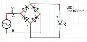
Now, let’s look at something more efficient called a Full Wave Bridge Rectifier. This is a very common rectifier circuit. Here is the schematic:
Now let’s look at what the load will see:
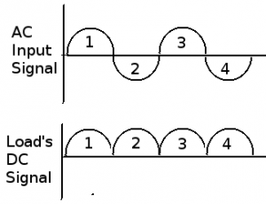
Notice our input AC signal in step 1. Compare this to the schematic. As our signal goes up, current flows in the direction of the “A” leg on the schematic. The diode will conduct and direct the + voltage to the anode side (+ side) of our LED. Look at Step 2. Current changes direction, and flows through wire “B” on our schematic into the rectifier. Current is still directed toward the anode of the LED. Step 3 and 4 are a repeat of step 1 and 2. You can see this rectifier directs both the upper and lower parts of the incoming AC signal to the + (anode) side of our LED.
Look at the DC signal the load receives, this is still not a pure DC signal, but it’s more efficient than the half wave rectifier, and current is always flowing in one direction. We call this fluxuation the “Ripple Current”. To filter the ripple current, we can use other components such as capacitors and inductors to get a more smooth signal.
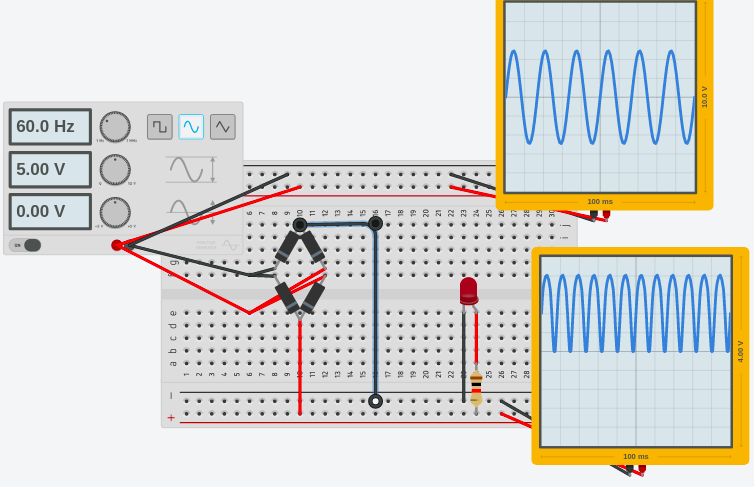
Let’s take a look at the raw signal on an oscilloscope
Light Emitting Diodes
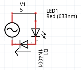
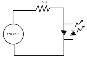
Another use would be for LED’s on an AC circuit. Although the LED itself acts as a diode, we need a second diode. The reason for this is to force conduction when the power flows in the opposite direction. If we do not use this diode, then there would be no current flow on half of the AC cycle. Obviously, if there is no current flow, then there is no voltage drop across the resistor. This could cause the high voltage to damage the LED. Consider the following circuit.
If you are not familiar with other calculations for basic electricity, see the beginner category to learn the basic principals of calculating resistance, current, voltage, and power.
For on-site industrial training, visit my employer’s website at atifortraining.com!
— Ricky Bryce