
Introduction to the COSMAC 1802 Addition Instructions
There are four COSMAC 1802 Addition Instructions: ADD, ADI, ADC, and ADCI. In this section we’ll take a closer look at each one of these instructions. Basically, the ADD statement will add a memory location to the value in the accumulator. The ADI is for immediate values. With this instruction, we can add any immediate value (constant) to the accumulator. There are also two instructions that deal with the carry DF (Data Flag) bit. DF is the 1802’s version of the carry bit. The carry instructions are ADC, and ADCI. ADC will add the accumulator to a memory location (plus the carry bit), ADCI is similar, but adds an immediate value to the accumulator plus the carry bit.
With addition, it’s important to understand what the carry bit is. If our math exceeds 255 decimal (FF Hex), then we set the carry bit. This is useful when working with large numbers.
Let’s take a look at each of these addition instructions individually to see how they operate.
I’ll be using the A18 Assembler for this post. I like to use that with Kwrite in linux, and take advantage of the auto reload feature.
ADD Instruction
The ADD instruction will simply add a memory location to the accumulator. Remember, in the 1802, the accumlator is the “D” register. The result of the ADD remains in the accumulator. Since this instruction uses the X register, it needs no other operands.
We must first be sure the X designator is set to the correct register. We do this with the SEX (Set X) Command. Here is a sample program that uses the ADD instruction.
The memory location we get data from will be 8200H. This is because we will set X to register 13. We don’t get data from register 13, but we get data from the memory location that register 13 points to.
MYMEMORY:       EQU     8200H;
BREAK:          EQU     2756h
RC              EQU     13

                ORG     8000H ; ORIGINATE AT 8000H
                LOAD    RC, MYMEMORY  ;SET UP RC TO POINT TO 8200H
                LDI     55H ;LOAD 55H INTO THE ACCUMULATOR
                STR     RC  ;STORE THIS 55H TO 8200H
                SEX     RC  ;SET X REGISTER TO 13
                LDI     02H ;LOAD ACCUMULATOR WITH 02H
                ADD         ;ADD ACCUMULATOR TO 55H (AT 8200H)
                STR     RC  ;STORE THE RESULT BACK TO 8200H;
                LBR     BREAK ;EXECUTE BREAK ROUTINE IN ROM.
                END
As you can see, we set a couple aliases for the program to make things easier to remember in the rest of our program. Our program will originate at 8000H.
We set the X Register to RC (In our aliases, we designate this as register 13). After that, we load the value of 2H into the accumulator. When we execute the ADD instruction, the processor will add the accumulator to the value in 8200H. The accumulator contains the result of this math. Therefore, if we assume that 8200H is already populated with the value of 55H, then our result will be 57H.
ADI (ADD Immediate) Instruction
The ADI instruction is very easy to use. It simply adds a static value to the accumulator. You might use this to increment a register. Here is a simple example. Let’s say that register RC contains the value of 8200H Remember, these are 16 bit registers, so we can get the high byte with GHI or get low byte with the GLO command. To increment the low byte of of register RC, we will use the following logic. For a complete program, you would obviously want to add the aliases and ORG statement as we did in the first example though.
          GLO  RC
          ADI  01H
          PLO  RC
Add with Carry Instruction (ADC)
The Add with Carry instruction (ADC) uses the X register just like the ADD instruction. The difference is that this instruction also includes the carry bit. We might use this instruction to perform math on larger numbers which require 2 memory cells (16 bits). Let’s take a look at how we would increment a memory cell where we need to increment a high byte due to carry.
LOWBYTE:  EQU  8200H  ;Assume this byte contains FFH
HIBYTE:   EQU  8201H  ;Assume this byte contains 01H
BREAK:    EQU  2756H  ;Break routine in ROM
RE        EQU  14
RF        EQU  15

          ORG  8000H
          LOAD RE, LOWBYTE ; RE contains the address of the lowbyte
          LOAD RF, HIBYTE  ; RF Contains the address of the high byte

          LDI  0FFH  ; Load FFH into D
          STR  RE   ; Store this to RE
          LDI  01H  ; Load 01H into D
          STR  RF   ; 8201 now contains the value of 01h

          SEX  RE         ; Set X to RE
          LDI  01H        ; Load 1 into D
          ADD             ; Add 1 to Low Byte (We don't need to look for carry)
          STR  RE         ; Store the result
          SEX  RF         ; Set X to RF
          LDI  00H        ; Load 0 into accumulator.
          ADC             ; If DF (Carry) Set, Add 1 to accumulator
          STR  RF         ; Store the result
          LBR  BREAK
          END
When you run this logic, you will see that 8200H contains 00H, while 8201 contains 02H. The answer of our addition is 0200H.
Add with Carry Immediate Instruction (ADCI)
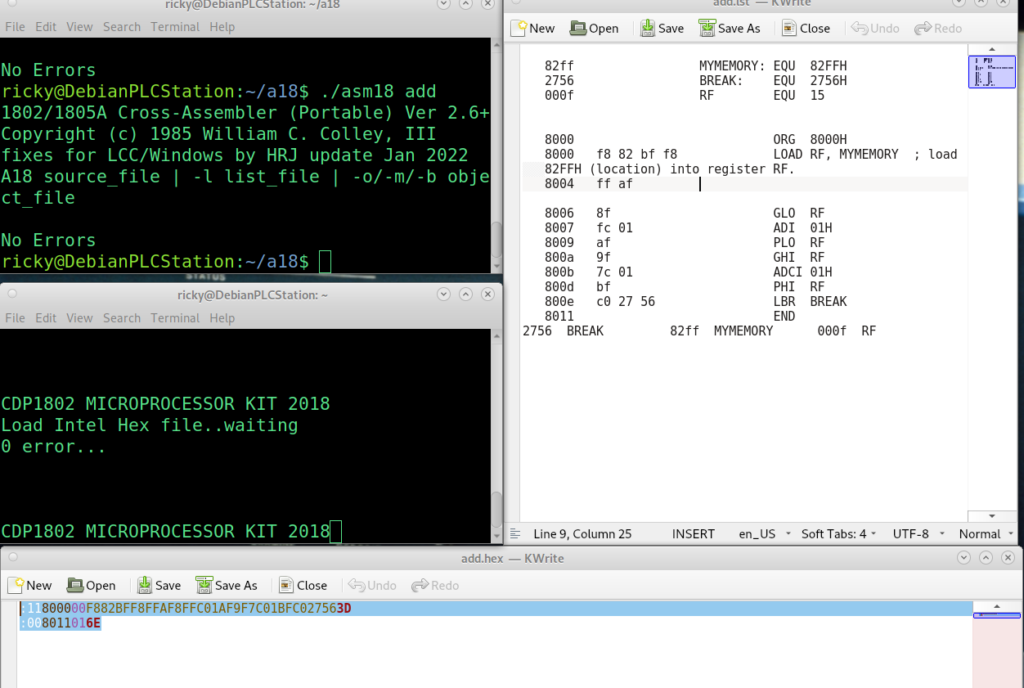
In this example, we’ll do something similar to what we did with the ADC Instruction. The ADCI works very similar to the ADI instruction, except that it also adds the DF bit. This time, we’ll increment a register. Let’s assume that register RF contains 82FFH. When we add 0 with carry, we’ll end up with 8300H.
Again, we need to do this one byte at a time. Remember, this is a register we increment, and not a value in memory. Keep in mind that registers simply point to memory locations (usually).
MYMEMORY: EQU  82FFH
BREAK:    EQU  2756H
RF        EQU  15


          ORG  8000H
          LOAD RF, MYMEMORY  ; load 82FFH (location) into register RF.

          GLO  RF   ;Get low value of RF
          ADI  01H  ;Add 1 (Carry will set)
          PLO  RF   ;store low byte back to RF
          GHI  RF   ;Get the high byte of RF
          ADCI 00H  ;Add zero + Carry
          PHI  RF   ;Store high byte back to RF
          LBR  BREAK  ;Break routine in ROM
          END
Experiment with this logic, and try some different values. These are important instructions to understand for most any program you will be writing.
Summary of COSMAC 1802 Addition Instructions
In short, there are 4 instructions. ADD will add the accumulator to a value specified in a register that is specified in X. Similarly, ADCI will add the value of a memory location in the same way. It just includes the carry (DF) bit.
The ADI simply adds a static (immediate) value to the accumulator, while ADCI also looks at the carry bit.
For more information, please visit the category page for the COSMAC 1802!
— Ricky Bryce