
Introduction to ControlLogix Analog
Discrete (digital) inputs and outputs are signals that are on or off. There is no middle state to discrete. These were good for switches, indicator lights, or motor starters, but if we want to measure a variable signal, we need an analog module. Examples of analog inputs include pressure transducers, potentiometers, or a tank level. Examples of analog outputs include a valve positioner, or a speed that we send to a drive.
Standard analog modules typically use a signal of 4 to 20 milliamps or 0 to 10 volts. Other types of analog modules would include a thermocouple or RTD module.
In our examples, here, we will be looking at analog input modules. Once you understand how analog input modules work, analog output modules will also be easy for you to set up. For analog output modules, then information is just written onto the module to control a field device.
Dangers
The analog input modules will typically act as a volt meter, or an ammeter. A volt meter is placed across a voltage source. To have minimal effect on a circuit, the volt meter will have a very HIGH resistance. An ammeter is placed in series with the circuit. For the ammeter to have minimal effect on a circuit, it will have a very LOW resistance. If you place a voltage source directly across an ammeter, a short circuit will occur.
Setting up a local ControlLogix Analog module (1756-IF16)
First, let’s talk about setting up a 1756-IF16 module. These modules are very easy to configure as the scaling can be done in the analog input module itself. The term “Scaling” means that we are converting raw data into usable engineering units.
When you add an analog module to the I/O Configuration tree, you will need to set up the required fields for the module. This includes the name, revision, slot number, and electronic keying for the module. If the module is already in your I/O Configuration tree, just right click the module and go to “properties” to see how it is configured.
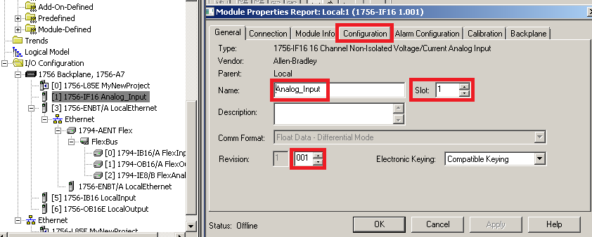
Next, we will consider a pressure transducer that is calibrated for 0 to 200psi. When the pressure transducer reads 0 psi, it will send out 0ma to the analog module. When it is reading 100psi, it will send out 10ma to our analog input module. Finally, if it reads 200psi, it will send 20ma to our module. The module must be configured to read these signals accordingly, so we’ll go to the Configuration tab of the analog module’s properties.
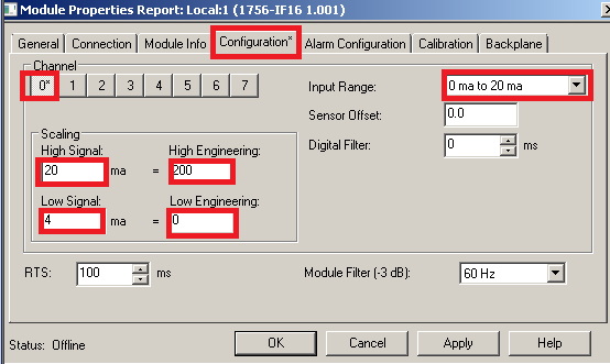
Finally, your analog module should be reading the correct pressure of 0 to 200psi.
About Raw Data
Some modules, such as the 1794-IE8 module are not sophisticated enough to do scaling at the module level. We have to do our own math in logic to convert raw counts into engineering units. Consider the following image:
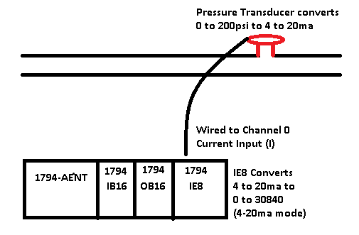
You will notice that the transducer converts 0 to 200psi to 4 to 20ma. When it gets into the analog module, though, it’s just raw data. The module is configured by the manufacturer to place a certain value into the controller tag. The range of the raw data will usually differ drastically from the calibration of the transducer in psi.
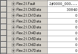
In this case, at 4ma, the module will place the value of 0 into our controller tag. At 200psi, the module will read 30840 instead of 200. All the module knows is that it gets 4 to 20ma. It does not know how the transducer is calibrated. We will have to do our own math to scale this value back into engineering units. Each type of module differs on the raw data that is placed into your controller tag. Consult the data format table for the module you are using (in the module’s manual) to find your raw data.
The reason you have such large numbers for your raw data is due to resolution. If the module only put 4 to 20 into your data table, you would only have 16 counts of resolution. Here, we have 30840 increments from 4 to 20ma instead of just 16 increments.
Configuring the 1794-IE8
If you have not done so already, set up your flex chassis that includes the 1794-IE8. You will find documentation on how to do this on the Ethernet I/O page.
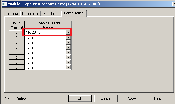
Once the 1794-IE8 module is in your I/O Configuration tree, we will right click this module to go to it’s properties.
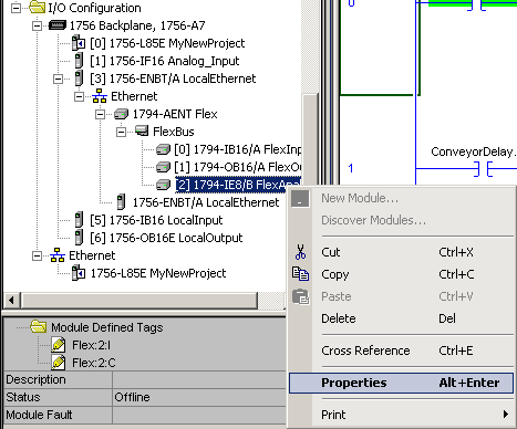
Next, we will go to the configuration tab, and set up channel 0 for 4 to 20ma. Remember, the transducer is placing 4 to 20ma on Channel 0.
Now, let’s go back to Controller tags, and look at our tag. Flex:2:I.Ch0Data, and we’ll see what data we are getting. Don’t forget to download if you configured this offline.
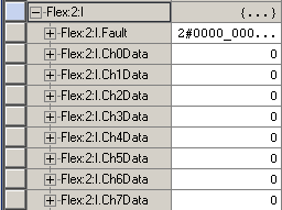
You will see our data is 0 because the transducer is reading 0psi, and therefore just putting 4ma on Channel 0 of the Input module. Next, we’ll put 200psi on the pressure transducer to see what value we get.
Scaling the Data
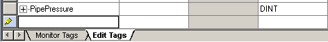
You will see that we get 30840. We will have to do some math on this value to get it to read 200 instead of 30840. Once we do the math, we will need a tag that we place the value into that represents our actual pipe pressure. While we are here, let’s go to “Edit Tags”, and create a tag called “PipePressure” We can leave this as a DINT. If we wanted a more precise answer with a decimal point, we could use the data type of REAL. DINT is OK for what we are doing here, though.
Now, we’ll add a CPT statement to our logic. The CPT allows us to enter a long expression, so we don’t have to perform the math functions one at a time. I’ll just add the CPT to the MainRoutine as follows:
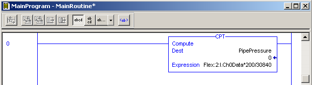
Be sure to finalize all edits, and as the pressure increases, your PipePressure tag will be reading the correct pressure of the pipe.
Note: you could also use the SCL function for your scaling if you have Function Block capability.
For your next step, check out some Compare Instructions, and learn how to integrate analog values into your projects!
— Ricky Bryce
Pingback: Setting up and adjusting a trend chart in Studio 5000
Ricky Bryce, I found your webpage very helpful, thanks for your dedicated time in explaining the funcions of Studio 5000. Can you help me on how to use SCL, and how to setup SCL.
Thank you for your suggestion! I’ve built a small tutuorial of the SCL command on this link:
http://bryceautomation.com/index.php/2019/11/09/controllogix-scl-command/
I’m glad you find the site helpful! — Ricky