
Introduction to SLC 500 Data Tables
SLC 500 Data Tables store values. You can think of data tables as “Data Registers” or “Variables”. In a default project, 9 standard data tables are created automatically. Each of these data tables can generally store up to 255 elements. We will discuss the purpose of each of the following data tables, and examples of instructions that typically utilize these files. Although some data files are interchangeable, I will discuss the most common use of these files.
It’s important to realize that to expand a data table you must be offline. In other words, lets’ say you only have 10 timers available. You need 20. You must go offline, then go to the properties of the T4 data file. Here you can increase the number of elements. When finished, you must download to get the changes into the processor. Keep in mind that when you download, your system goes down.
Additionally, in the SLC-500, you can create additional data files. The maximum file is 255.
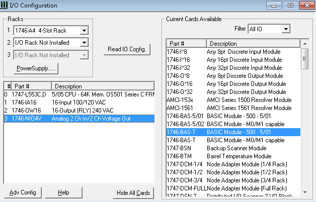
For the following examples, I have set up the I/O Configuration is as follows:
O0 — Output Data File
The output data file stores the outputs that we want to write to the output modules (aside from forces). Toward the end of the processor scan, the processor sends theoutput data table to the output modules to energize or de-energize outputs. The processor will also write values to the analog output modules.
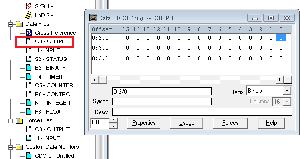
An example of an instruction that uses the output data table is the OTE (Output To Energize Instruction).
I1 — Input Data File
The input data files shows the status of the inputs that connect to the input module (aside from forces). The processor reads inputs during the first part of the processor scan cycle.
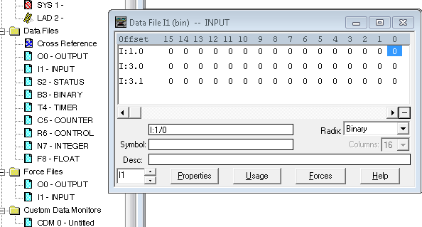
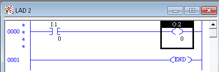
An example of an instruction that utilizes the input tags is the XIC (Examine if Closed) instruction.
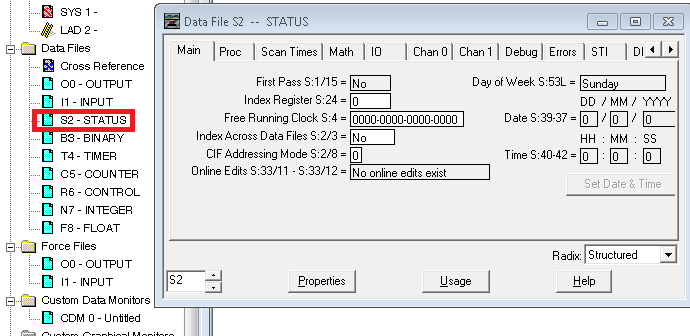
S2 — Processor Status
The S2 Data file stores the processor status. This includes the time of day, I/O fault conditions, and a battery low bit. Other examples are the status of forces, math overflow, etc. Each element of the S2 status file has a memory location. You can use these memory locations in your logic. For example, let’s say that you have some logic that you need to execute at midnight. Use Data Tables S:40, S:41, and S:42 in your logic.
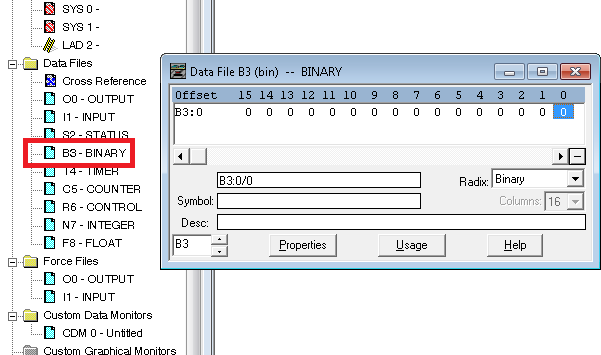
B3 — Binary File
Think of the B3 file as “Internal Coils”. When a certain condition is met, such as “Guard Doors Closed”, a bit is set. The programmer declares what they will use each bit for. They will use this bit through out the project, anytime we need to know if all doors are shut, or if a door is open.
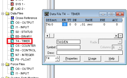
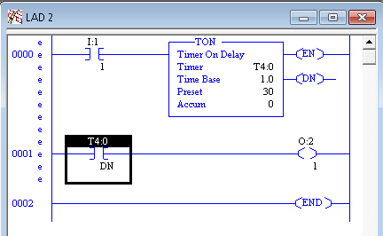
T4 — Timer File
We use the timer file for timer instructions, such as TON, RTO, and TOF. Each element of the timer file contains an EN (Enable Bit), TT (Timer Timing bit), and DN (Done bit). Each element also stores the PRE (preset) and ACC (Accumulated value). Be careful not to store a negative value in a timer. This will fault the processor. The maximum preset is 32767. The total number of time available on a timer depends on your time base setting. The preset times your time base is the number of seconds the timer will time.
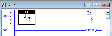
Here is an example of how a timer might be used in logic.
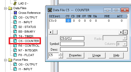
C5 — Counter Table in SLC 500 Data Tables
We use the counter file with counter instructions such as the CTU (Count Up) and CTD (Count Down). Each element of the counter file contains the following members:
- CU — This is the “enable” bit for the CTU instruction.
- CD — This is the “enable” bit for the CTD instruction.
- OV — This is the overflow bit, and goes high when the counter exceeds 32767. This is the maximum value for a 16 bit signed integer.
- UN — This is the underflow bit, and goes high when the counter drops below -32768.
- UA — Update Accumulator. We use this for High Speed Counters of a fixed SLC unit.
- PRE — This is the counter’s preset.
- ACC — The counter’s accumulated value.
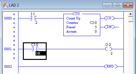
For example, here is how a counter might be used in logic:
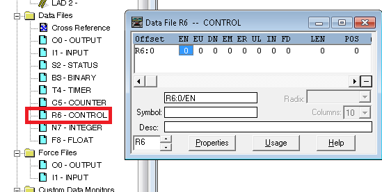
C6 — Control File
The C6 data file is a generic table that used with several advanced instructions. This includes sequencers and other file instructions that need to keep track of position, and the length of the file we are operating on. The C6 file contains the following members:
- EN — Enable bit
- EU — Enable Unload bit
- EM — Empty Bit
- ER — Error Bit
- UL — Unload bit
- IN — Inhibit bit
- FD — Found bit
- LEN — This is the length of the file being operated on.
- POS — This is the instruction’s current position within a file.
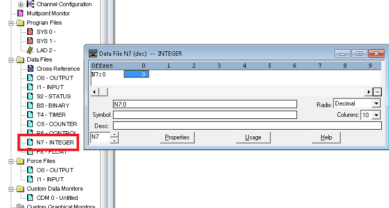
N7 — Integer File
We typically use the integer files to store numbers, such as the scaled value of an analog input. The values can range from -32768 to 32767. These are 16 bit signed integers.
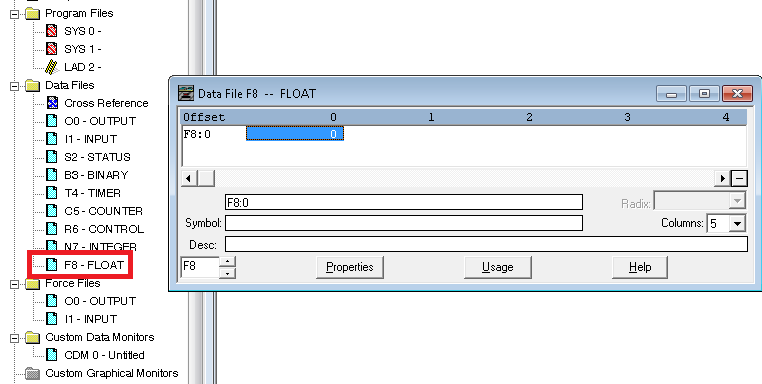
F8 — Floating Point File in SLC 500 Data Tables
When you require more precision than what the Integer file provides, use the a floating point file. The F8 file uses more memory (32 bits per element), but allows for decimal points in numbers. It’s also useful when working with very large or very small numbers.
On the B3 and higher data files, you can go to the properties to adjust the number of elements in the table. However, if you are offline, and declare a valid data table address of an existing table, RSLogix will automatically expand the data table to include the new elements that you are using in logic.
The “Usage” button is a very good tool to find out what addresses are already in use by the project. This helps you to see what addresses are available for future use.
Finally, the RADIX selector is a good tool for changing the numbering base of the table between Binary, Decimal, Octal, and Hexadecimal. The RADIX does not direct affect the program. It simply changes the way that you are viewing data in RSLogix.
Furthermore, visit the SLC-500 Category Page for more information on the SLC systems.
— Ricky Bryce