
Introduction to COSMAC 1802 Flasher Logic
In this section, we’ll write a simple program for a COSMAC 1802 Flasher. We’ll keep this as simple as possible, and use a couple delay loops. In this case, we’ll just use the Q output of the processor. The most important commands for this to work are the SEQ (Set Q) and REQ (Reset Q) instructions. I’m using the CDP1802 Microprocessor kit, but this should work with about any setup.
I’ve already installed the A18 assembler in Debian 11. Windows is another option though. The A18 assembler code comes with an EXE file for Windows. We’ll be using this assembler later in the post.
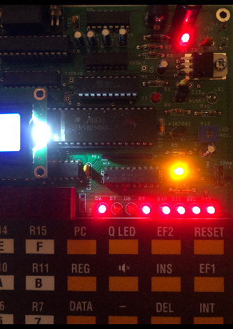
On the CDP1802 Microprocessor Kit, the yellow light connects to your Q output.
Set ORG and Registers
I like to start off any program by stating the starting memory location the code will reside at. For the CDP1802 Kit, this will be 8000H. Your set up may be different. Additionally, we will declare the aliases for our registers. This will make our programming a bit easier. This section is just for the assembler, and does not produce any direct output to the object code. Keep in mind, these 16 registers are the “Scratchpad” registers of the 1802 processor.
	org	8000H
R0	EQU	0
R1	EQU	1
R2	EQU	2
R3	EQU	3
R4	EQU	4
R5	EQU	5
R6	EQU	6
R7	EQU	7
R8	EQU	8
R9	EQU	9
RA	EQU	10
RB	EQU	11
RC	EQU	12
RD	EQU	13
RE	EQU	14
RF	EQU	15
Create Your Delay Loops
Without delay, or logic will run so fast that we probably wouldn’t see the light flash. We’ll create some delay loops that will add about a 1 second delay. You can adjust the number of times that each delay loop executes. In this case, the entire delay loop takes about 1 second to complete. To change the delays, just adjust the value in INIT0, INIT1, or INIT2.
INIT0:		LDI	010H
DLY0:		PLO	RC
INIT1:		LDI	010H
DLY1:		PLO	RD
INIT2:		LDI	0DEH
DLY2:		PLO	RE
		DEC	RE
		GLO	RE
		BNZ	DLY2
		DEC	RD
		GLO	RD
		BNZ	DLY1
		DEC	RC
		GLO	RC
		BNZ	DLY0
Set or Reset Q
At this point, we are ready to execute the SEQ and REQ instructions. This will set and reset the Q output on the processor. If you connect an LED to pin #4, be sure to add a resistor in series with the LED.
The BQ command checks to see if Q is set. If it is, then we jump to the OFF Label, which turns OFF the Q output with the REQ instruction. IF the Q Output was off, then the BQ instruction is false, and we execute the SEQ instruction to turn it on.
	BQ    OFF
ON:	SEQ
	BR    INIT0
OFF:    REQ
        BR    INIT0
        END
In this case, we’ll save our work as “flasher.asm”. After that, you can run the assembler on your file to make sure there are no errors. You can either upload the hex file, or look at the list file. The flasher.lst file will list the OPCODES that you can enter manually.
Summary of the COSMAC 1802 Flasher
In short, we just declare some registers, and create a delay. If the output was ON, then we shut it off. Likewise, if the output was OFF during the previous scan, then we turn it on. This is a good program to get you started with programming your COSMAC 1802.
List File
Here is the output of the LIST file in case you wish to enter your program manually:
   8000   f8 10         INIT0:		LDI	010H
   8002   ac            DLY0:		PLO	RC
   8003   f8 10         INIT1:		LDI	010H
   8005   ad            DLY1:		PLO	RD
   8006   f8 de         INIT2:		LDI	0DEH
   8008   ae            DLY2:		PLO	RE
   8009   2e            		DEC	RE
   800a   8e            		GLO	RE
   800b   3a 08         		BNZ	DLY2
   800d   2d            		DEC	RD
   800e   8d            		GLO	RD
   800f   3a 05         		BNZ	DLY1
   8011   2c            		DEC	RC
   8012   8c            		GLO	RC
   8013   3a 02         		BNZ	DLY0
   8015   31 1a         		BQ OFF
   8017   7b            ON:		SEQ
   8018   30 00         		BR    INIT0
   801a   7a            OFF:    REQ
   801b   30 00                 BR    INIT0
   801d                         END
For more information, please visit the Vintage Computer Category Page!
— Ricky Bryce