
Introduction to the MOSFET
A MOSFET is a Metal Oxide Semiconductor Field Effect Transistor. That might sound intimidating, but basically, a MOSFET is a switch. There are two types of MOSFETS: Enhancement mode, and depletion mode. Unquestionably, the most common type of FET is the Enhancement mode. We will discuss this type of FET in this document.
It’s important to realize that a MOSFET is a voltage controlled device. In contrast, a BJT transistor is a current controlled device.
It’s also equally important that you know a MOSFET has a gate capacitance. The gate capacitance will hold the MOSFET on unless you sink the gate to ground in an NPN device.
Let’s look at the following diagram I made with Tinkercad!
Turning on the MOSFET
This circuit is for the purpose of this demonstration only. If both switches are on at the same time, you would have a short circuit, but we will only be turning on one of them at a time for this demonstration.
Notice that on the brreadboard, we have two switches. The switch on the left will put a + voltage on the gate, while the switch on the right will put GND to the gate. When either switch is in the left position, it is on.
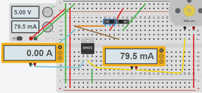
Here you can see that we are applying 5v to the base of the FET(5v switch is on). Pin 1 is the base, Pin 2 is the drain, and pin 3 is the source. The MOSFET has a very high gate impedance. This means that it takes practically no current to hold the gate high. In fact, the only current that really flows is for a short time due to the capacitance of the gate. The motor is clearly energized with no current flowing into the gate. It’s important to realize this is a logic level FET. This means we can turn it on with 5v or less. Different types of semiconductors have different thresholds, so check the datasheet for the MOSFET that you are using.
Partial conduction
It’s also important to realize there is a small region of voltage where the semiconductor can partially conduct. Although this can be good in some applications, you have to be very careful with heat dissipation.
Floating Gate
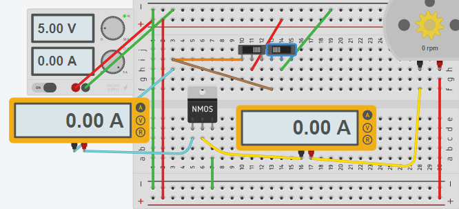
Be careful with MOSFETS! Notice what happens when I shut the switch off.

Nothing is currently connected to the gate, so the gate is “floating”. Due to the capacitance of the gate, the Field Effect Transistor remains in the ON state. If you wish to control the FET with a single switch, it’s a good idea to place a resistor across the gate and source. In my projects, I usually use a 3034 MOSFET, and will place a 15K resistor between the gate and source to prevent the gate from floating.
Turning the MOSFET off
If I place ground potential on the gate, the MOSFET will no longer conduct, and the motor will shut off.
Because there is no current to the base, and a logic level MOSFET can conduct a large amount of current, the FET is ideal for switching large loads using microcontrollers. It’s not a bad idea to place a current limiting resistor on the gate, however to limit the inrush current when the gate capacitance is charging.
One challenge of FETS is also heat dissipation. By looking at the datasheet, you can find the Rds (Resistance drain to source). Also look at the heat generated in degrees celsius/watt. Another thing to keep in mind is the maximum junction temperature on the datasheet. With all of that information, you can determine if a heat sink is required. Calculate the power by Rds times current squared. This will give you the power in watts. Because you know the degrees per watt, and the maximum junction temperature, you can ensure you are not overheating the semiconductor.
Final Circuit
Here is an example of the completed circuit with a single switch. When the switch is on, we run + through the 1K resistor, then to the gate. In this configuration, the maximum current draw of the switch can only be 5mA. You will also notice a 15K resistor. This “bleeds” the gate voltage to ground when the switch is shut off.
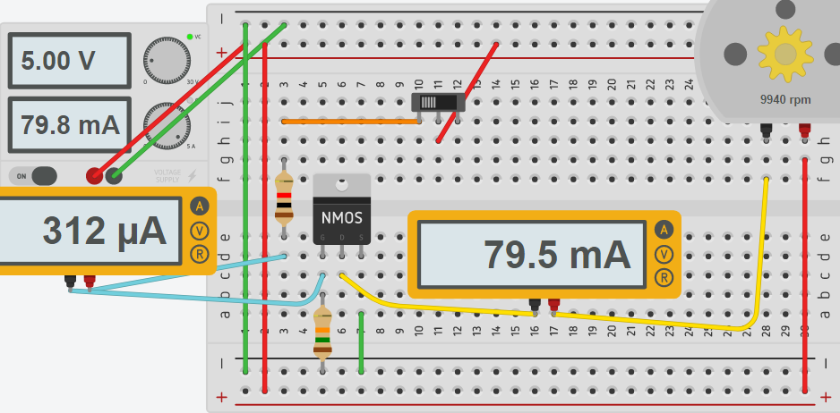
You will notice a little current flow to the gate this time. This is due to the 15K resistor. Even though we are effectively wasting 312 MicroAmps when the motor is turned on, the gate is no longer floating.
— Ricky Bryce