
Introduction to ControlLogix Timers
ControlLogix timers are used to delay events, or to time events. There are three timers in the ControlLogix processor. The TON (Timer On Delay) delays an event from turning on. Next, the TOF (Timer Off Delay) Delays an event from shutting off. Then we have an RTO (Retentive Timer On Delay) which is used to keep track of run time.
Typical Examples:
The TON instruction will delay an event from taking place such as a conveyor starting. When the operator presses a start button, you might want to blow a warning horn for a few seconds before the conveyor actually starts. Also, if a system on your equipment goes into an alarm condition, you might delay informing the operator for a few seconds to prevent nuisance alarms.
The TOF instructions delays an event from shutting off. A good example of this is a blower on a motor to keep the motor cool. When the motor starts, the blower will start. When the motor shuts off, the blower might still run for a few minutes to cool down the motor. Another good example is for energy savings. If no valves on a system have moved in the last 15 minutes, it might be OK to shut off the hydraulic pump.
The last timer we will cover is the RTO. This timer works almost exactly like the TON. The exception is that it keeps the accumulated value when the rung goes false. This might be used to keep total track of machine run time for maintenance. For example: After a system accumulates a total of 6 hours of run time, a light might come on indicating that PM is needed. When you perform the PM, press a reset button to start the timer again. This can also be used to engage an automatic lubrication system after a certain amount of run time.
Create tags for the ControlLogix Timers
Except in very special cases, we need to create a new tag every time we have a new TON, TOF, or RTO instruction in logic. If you use the same tag on two timers would normally cause them to interfere with each other. When we create the tags, we will give them a TIMER data type. A data type is just the way the data is structured with in tag. A Tag with a BOOL datatype has just one bit available. A tag with a DINT (double integer) data type has 32 bits available. A tag with a TIMER datatype will have a perset, accumulated value, EN (Enable) bit, DN (Done) bit, and a TT (Timer Timing) bit.
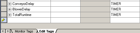
Let’s go to Controller Tags, and in “Edit Tags” mode, we’ll add the following tags:
Bit Operation
Next, expand one of the tags (click the +), and we’ll see all of the components of the timer.
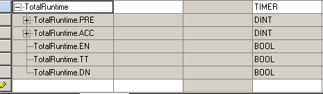
Notice that we have two DINTs. These are tags made up up 32 bits that will store numbers (integers). The preset is how much time (in MilliSeconds) the timer will run. So if we want a preset of 10 seconds, we will place 10000 into the preset later in this post. Our ACC is the accumulated value. The timer instruction will use this memory location to keep time. Next we have the Enable bit (EN), which will be true when the timer instruction is true. This applies to all three timers. Then we have the Timer Timing bit (TT) which is true while the timer is running up the accumulated value toward the preset.
The way the DN bit works depends on the type of instruction you are using. For both the RTO and TON, the DN bit is off when the instruction is false. When the rung goes true (logical power to the timer), the accumulated value will run up toward the preset. When the accumulated value reaches the preset, the DN big goes true.
For the TOF instruction, the DN bit goes true immediately when the timer is energized. When the timer goes false, the DN bit will shut off later (after the accumulated value reaches the preset).
The TON Instruction
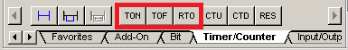
Let’s add the following logic. You will find the TON instruction on the timer/Counters tab of your instruction toolbar.
When adding the logic, set the preset to 10000 (10 seconds)
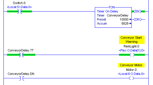
Notice that when we energize the timer with switch.0, the EN bit goes high. The TT bit also goes true, and we get a warning that the conveyor is about to start. The accumulated value starts to run up toward the preset. If we were to shut off the timer at this point, the EN and ACC would go back to zero. Let’s keep it running though, and look what happens next when the accumulator reaches the preset:
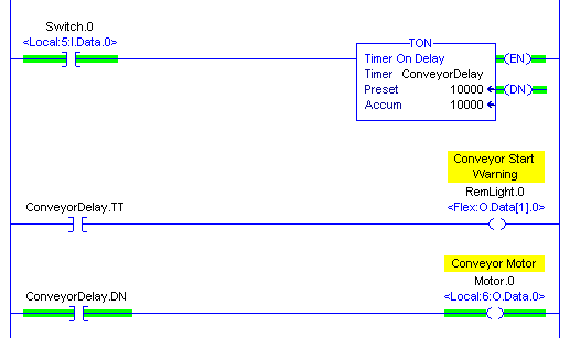
Notice when the accumulated value reaches 10000, the DN bit goes high. At this point, the TT bit shuts off. The EN bit is still on because the TON is still energized. In the second rung, we see that the DN bit also went true, and the motor started.
The TOF Instruction
Add the following logic. We will set the Preset to 10000 (10 Seconds) again, and we will explore how the TOF instruction works.
Look what happens when we turn the switch on to energize the TOF instruction:
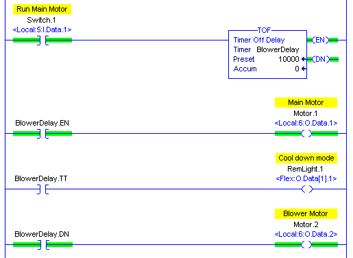
When we energize switch.1, notice the EN and DN bits go true right away. As you can see, the Main Motor and the Blower motor both begin to run. Now, let’s shut off switch.1 to see what happens.
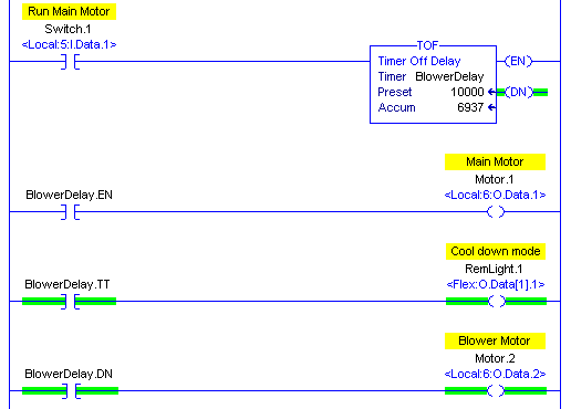
After switch.1 is shut off, the accumulator value begins to run up. The TT bit goes true, and we are using this to indicate that we are in cooldown mode. Even though we do not have the TOF instruction energized, the DN bit is still on at this point. The Blower motor is still running. Now let’s see what happens when the accumulated value reaches the preset:
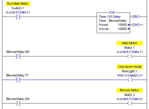
Once the timer has timed out, all of the bits are shut off, but the accumulated value will remain at the preset until the rung goes true again.
Warning!! Even though a RES (reset) instruction is available, it’s not recommended to use on the TOF instruction because of the nature of the DN bit. This could cause unpredictable operation.
The RTO Instruction
The RTO instruction is the retentive timer. It works almost the same as the TON instruction, except that when the rung is shut off, the accumulated value remains where it left off. When the rung goes true, the accumulated value will start to time again. When it times out, the DN bit goes true. We will use a RES (reset) instruction to reset the timer because it does not automatically reset when the rung goes false.
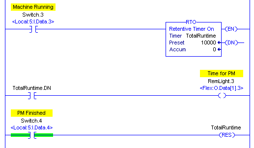
Let’s add the following logic:
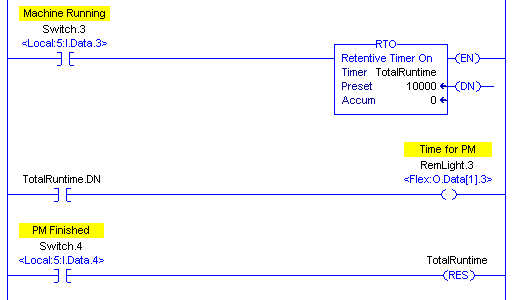
Now, let’s see what happens when we energize switch.3:
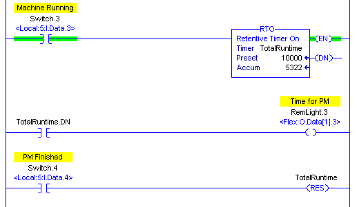
Now shut off switch.3. You will see that the accumulated value did not reset to 0 as the TON would have.
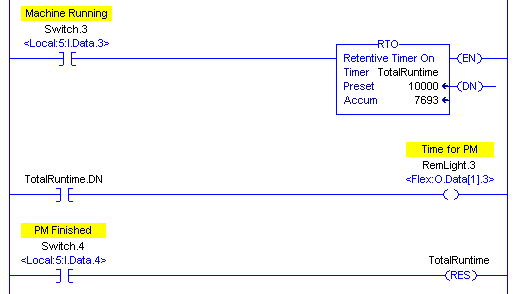
Now, we’ll turn switch.3 back on to let the timer finish timing.
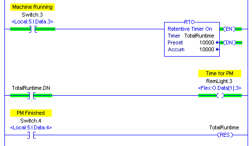
Finally, we’ll shut off the machine to do our PM, and once the PM is complete, we will press switch.4 to reset the PM timer.
Summary of ControlLogix Timers
In short, we use ControlLogix timers to delay events, or to time events. We can delay an event from turning on with the TON instruction. Likewise, we can delay parts of our equipment from shutting off with the TOF instruction. Use the RTO instruction when you wish to time events such as machine run time for maintenance.
By far, the timer we see the most often is the TON instruction. We might see a few TOF instructions in every program, and maybe a couple RTO instructions.
Remember, when the TON instruction goes true, the DN bit goes true later. It’s important to realize that the TOF instruction works much differently. When the TOF instruction goes true, you get a DN bit right away. Once the timer shuts off, the DN bit shuts off later.
Remember the RTO works exactly like the TON instruction, except that it retains it’s accumulated value. In other words, when the timer goes false, the Accumulator does not reset. Use the RES instruction to get the accumulator back to zero.
For more documentation on ControlLogix, please visit the ControlLogix category page!
— Ricky Bryce
Pingback: How to write logic to flash a bit in the ControlLogix processor.
Pingback: PLC-2 On Delay Timer Instruction - Bryce Automation