
Introduction to ControlLogix DF1 Messaging
In this section, we’ll discuss ControlLogix DF1 Messaging to an SLC-500 processor. Connect the Serial port of an L6x or earlier ControlLogix to the serial port of an SLC-500 processor. We’ll use a NULL MODEM cable in this case.
Albeit, there are faster communication protocols available, this may be the least expensive and easiest method of communication in many cases.
Overview of the SLC-500 project
To simplify, we’ll just use the default settings of the SLC-500. Start a new project in the SLC if you haven’t already. Be sure your project is valid, and that you have read the I/O Configuration. As an illustration, we’ll look at the Channel Configuration of a default SLC-500 project. First, on the general tab, be sure the channel is in SYSTEM mode.
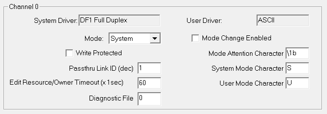
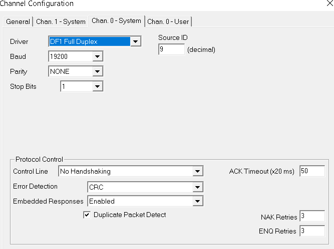
Notice the settings of the Chan. 0-system tab. We will need to refer to some of these settings when configuring the ControlLogix serial port.
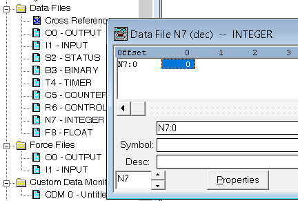
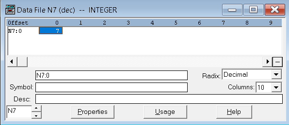
Also take note of the N7 data file. By default, only one element is available. We will write to this one element from the ControlLogix.
Finally, download the project to the SLC, and go to run mode.
Configure the ControlLogix Serial Port
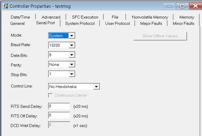
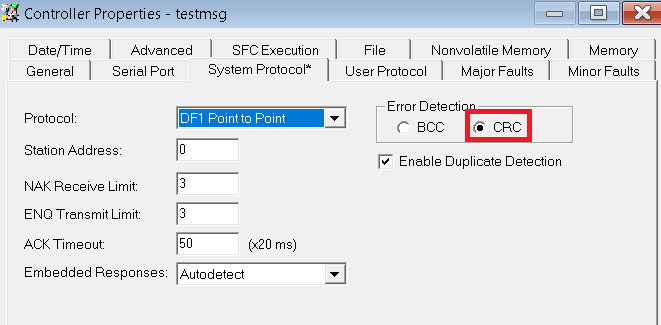
For example, I’m starting off with a default ControlLogix project. Right click the controller, and choose “Properties”. On the “Serial Port” tab, be sure the settings match that of the SLC’s Channel 0.
On the “System Protocol” Tab, we will change the error checking to CRC to match that of the SLC.
Set up the Tags
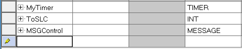
Before we begin, let’s create a few tags that we will need in logic. Set up the following tags with the shown data types below. We’ll create a timer to trigger the message instruction. Also, we need a tag to get data from, and a control element to allow the MSG instruction to store it’s status. Remember that our goal is to take the value of the tag “ToSLC”, and send that to the SLC.
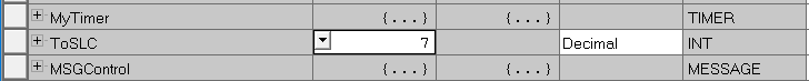
For example, we’ll go to “Monitor Tags”, and enter a random value that we can test later on.
Create the Logic for ControlLogix DF1 Messaging
At last, we’ll create the logic as shown below. The timer will pulse every 100ms, and trigger the MSG instruction. For this purpose, will just add this to the MainRoutine.
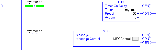
On the MSG instruction, click the Ellipsis (three dots). This is the grey box within the message instruction.
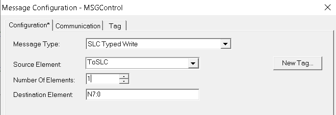
In the message configuration, specify this as a SLC typed write. Keep in mind our goal. We need to take data from the “ToSLC” Tag, and place that data into N7:0 in the SLC. We’ll set up the “Configuration” tab as follows:
Next, go to “Communication”. We need to specify a path.
We separate the segments of a path by the comma. First, specify the number 2 in the path to come out of the front port of the processor. Then specify the ID of the SLC serial port which is 9. Therefore, our path is 2,9.
Go back to the SLC-500 software (RSLogix 500). Be sure your SLC received teh value that we sent it!
If you have other questions, please visit the page for ControlLogix Messaging, or visit the post on a SLC initiated message to ControlLogix!
— Ricky Bryce