
Introduction to PlantPAx 4 Interlocks
With PlantPAx 4 Interlocks, if any condition changes on our equipment, we might shut off an output. For example, if a lube pump shuts off, you might shut off an output for a motor. We might also interlock valves, so we cannot energize the open and close solenoids at the same time. With this in mind, don’t confuse Interlocks with Permissives. Permissives typically allow and output to energize in the first place. In contrast, and Interlock will typically shut off an output under certain conditions.
Interlocks in Logic
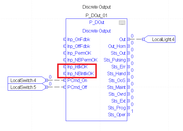
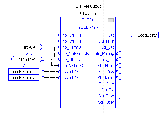
Take the case of an output instruction. Notice that we have two inputs to this instruction for Interlocks. One input tells us the interlock is OK. Likewise, we have another input that tells us the Non-Bypassable interlocks are OK. The operator can bypass certain interlocks if we allow them.
Import the interlock add-on instructions
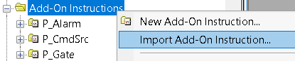
In order to use Interlocks in logic, first we need to import the P_Intlk Add-On Instruction. Right click the Add-On instructions in your controller organizer window. Choose to “Import Add-On Instruction”
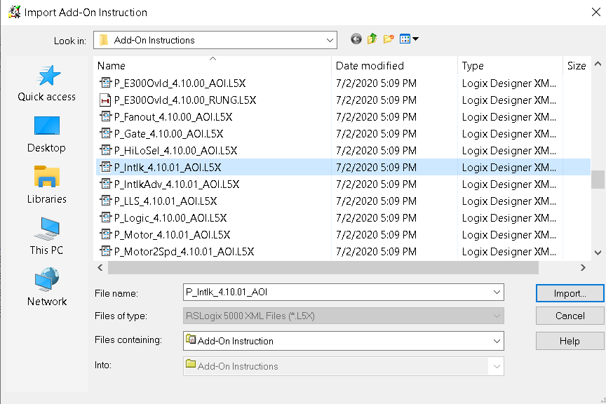
Choose the P_Intlk Instrcution, and click open. At this time, we’ll just leave the settings all at default.
Create a new sheet, and label this sheet as “Interlocks”.
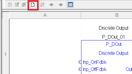
The name of the sheet is in your upper right hand corner of the Function Block editor.

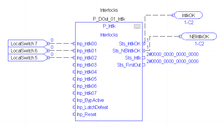
At this time, add the logic for your Interlock. In this case, I’m just using discrete switches. These switches represent field devices you will find on an actual project. You will need the P_Intlk instructions, three Input References, and 2 Output Wire Connectors. Your output connectors will not verify yet. At this point, we have not yet set up the input connectors. Most important: You MUST change the name of the tag for the P_Intlk instruction. In order for PlantPAx to find the interlock, it must have the exact same name as the instruction it is tied to followed by “_Intlk”.
Back on sheet 1, add your Input Connectors into the P_Dout instruction.
Download your work to the processor, and go to Remote Run mode.
Add the P_Intlk faceplates
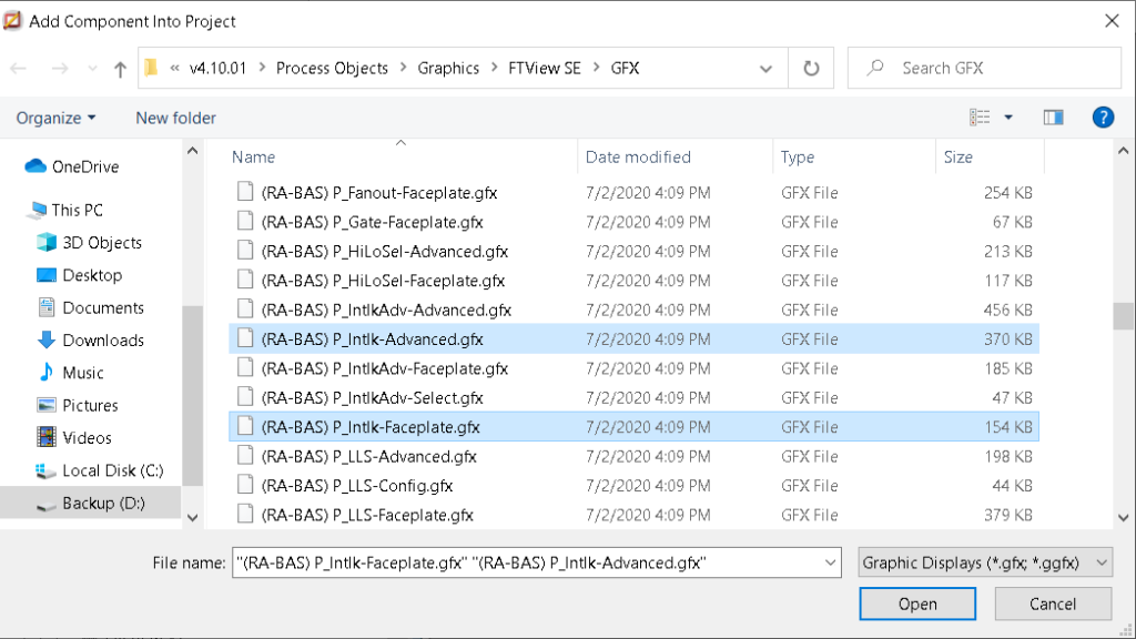
Our next step is to add the displays. In order to do this, right click “Displays” under “Graphics”, and Import component into application. Import the P_Intlk-faceplate, and P_Intlk-Advanced.
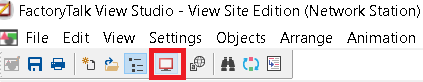
That’s all we need to do! Now launch the client.
Using the Faceplates
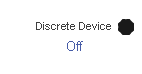
When an Interlock is not made, you will see a “Stop Sign” on the output object.
With this in mind, be sure you are logged in, and double click the output object to bring up it’s faceplate.
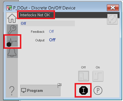
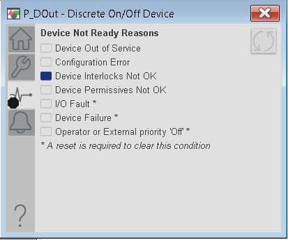
Notice the “Stop” symbol on the diagnostic icon, and on the Interlock icon. First, let’s open the diagnostic faceplate.
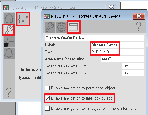
With this in mind, go back to the home screen. We need to enable navigation to the Interlock faceplate. Go to “Maintenance” then “Advanced Properties”. Then click on the HMI Configuration icon. Be sure to document the tag name of the P_DOut instruction, and select “Enable Navigation to Interlock object”. You can also change the name of the label on this faceplate. Be patient when enabling the interlock object. After you click the checkbox, it will take a few seconds to appear.
Next, go back to the Home screen. Open the Interlock object, then go to Maintenance. Finally, on the “Display Advanced Properties” screen, change the labels on the Interlocks. At this time, you will also allow a bypass for any interlocks that are bypassable or must be reset. You can also set the “OK” state to 0 or 1.
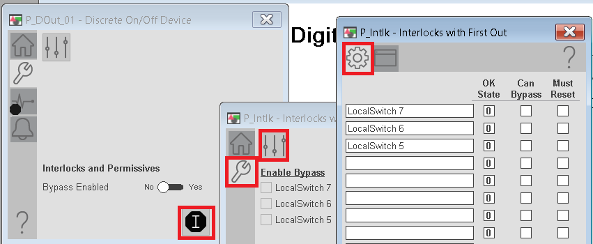
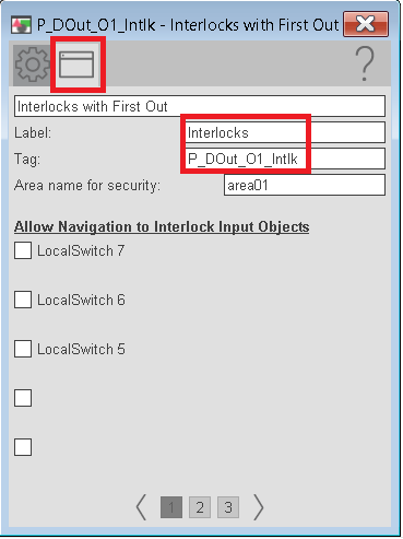
At this point, go to the HMI Configuration tab. Document the name of the Interlock tag, and allow navigation to any input objects. If you allow navigation to Input objects, you must specify the tag for that object.
For more information, visit the PlantPAx category page.
— Ricky Bryce
Pingback: PlantPAx 4 Motor Operated Valve (P_ValveMO) - Bryce Automation
Pingback: PlantPAx 4 Analog Outputs (P_AOut) - Bryce Automation
Pingback: PlantPAx 4 Motors (P_Motor Instruction) - Bryce Automation