
Introduction to Transistors
Transistors can act as a switch, or as an amplifier. Using a transistor, we can control a large load with a small amount of current. Micropressors, such as the Atmega328 are allowed a maximum of 40mA of current per output pin. Loads such as a motor, however, will consume more current than 40mA. Therefore, we need a device that can take a small amount of current, and control the larger amount of current.
There are two main types of basic transistors: NPN and PNP. The NPN interrupts the negative side of the load, and we control the amount of current through the load with positive current. In contrast, the PNP controls the positive side of the load. In the PNP transistor, a negative current flow at the base controls the current of the load.
We MUST control the amount of current to the base of the transistor. We do this with resistance. Without resistance on the base, you will likely damage the transistor and/or microprocessor!!!
Another application would be a transistor radio. The signal coming in from the antenna provides a very small amount of current flow. By using a transistor, we can use the small amount of current from the antenna to control a larger load, which would be a speaker!
Example (50% power)
At any rate, let’s look at the circuit below to see what is happening with the transistor. I generated these images with Tinkercad.
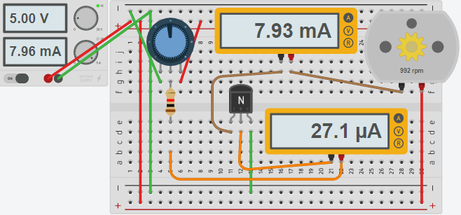
First, let’s look at the potentiometer. We have negative voltage on one side, and positive voltage on the other. When the wiper is fully counter-clockwise, the wiper (middle pin) is at 0 volts. When the potentiometer is fully clockwise, the wiper is at 5 volts. The more voltage we have from the wiper, the more our current flow will be to the base of the transistor. Notice there is a 1K resistor to limit current to the base. The example above is an NPN transistor. Our pin on the left is called the Collector (Pin 1). The middle pin is called the base (pin 2). Pin 3 is called the emitter. The motor’s current flows from the collector to the emitter, and is controlled by the current we provide at the base.
In this case, our potentiometer is set to about 2.5 volts. The current flows through the bottom ammeter, before going to the base. You can see the current to the base is 27.1 MicroAmps. This is also the current flowing out of the wiper on the potentiometer (the controlling device).
Secondly, let’s look at the current flowing into the motor. This is much higher at 7.93 mA. The current is 293 times higher, so we would say this transistor has a gain of 293 (hFe).
Example (75% Power)
Now we’ll turn the potentiometer fully clockwise.
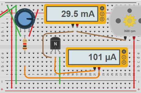
You can see that our base current has increased, and the speed of the motor has increased.
There are many different types of transistors with varieties of current ability, and gain. Be sure to select the transistor that suits your application’s needs!
To test transistors, you can use an inexpensive meter such as the MK-328, or Mega328!
— Ricky Bryce