
Introduction to the SLC-500 ASCII Write (AWT)
We use the SLC-500 ASCII Write (AWT) instruction to write data through the serial port of the processor. Since ASCII is a world wide standard, this ability greatly increases our ability to communicate with other devices. For example, many weigh scales support ASCII, some printers, and even any PC can read and write ASCII Data.
I’m just going to keep this lab simple, and we will write the text, “Hello World” to a PC. Experimentation should not be done on running equipment. This document is an example only. Be sure you are using Channel 1 to go online with a 5/03, 5/04, or 5/05 as we will use channel 0 for ASCII.
Prepare Channel 0
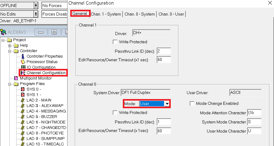
At this time, we’ll go to Channel Configuration, and on the “General” tab, set the mode to “User”.
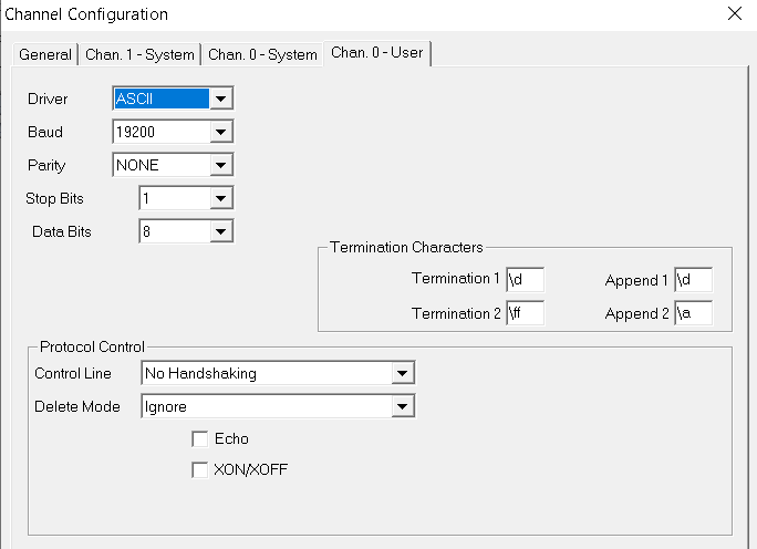
Next, go to Channel 0 User Tab, and take note of the settings. I’m just going to leave all the settings at default for example.
Create Data Tables
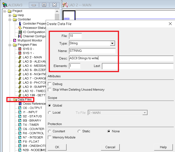
Before we begin, we’ll drop offline. In the SLC, we must be offline to create a data table. Right-Click the Data table folder, and create a new data table as follows:
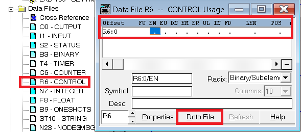
For this exercise, one element will be enough. We will also need a control element though, so open R6 to make sure we have a free control element. Click the “Usage” button. This will become a data file button when you are viewing usage. If your file looks like this, then the control element is not in use. If you have W’s and X’s, on all of your elements, just create a new element to use by going into the properties of the file.
Likewise, check your T4 timer file usage, and add a timer if needed.
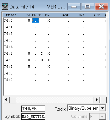
In this case, T4:8 and T4:9 are available.
Next, open the ST10 data file, and type “Hello World “. I intentionally placed a space after the last character, so the total characters are 12.
Write the Logic
We are ready to write the logic. I will set up my logic as follows:
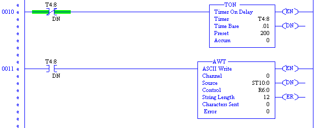
We are writing out of Channel 0, which is the Serial Port. The data file we created as the source is ST10:0, and the control file is R6:0. Remember that our string length was 12 characters including 2 spaces.
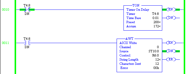
I’ll download my work, and go to run mode.
Prepare your PC to receive the text
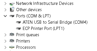
Next, we’ll set up the PC. In this case, I’ve connected a null modem cable from channel 0 of the processor to a USB to Serial adapter. I do need to know the COM port the USB to serial bridge appears on though. Obviously, we’ll go to Device Manager for that.
I’ll hit the + or down arrow next to “Ports”. We see the adapter is on COM4.
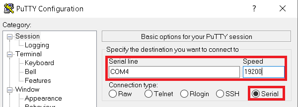
I like to use PUTTY, but you could also use Hyper-Terminal, or other terminal that you are familiar with.
I’ll set the communication type to Serial, set the com port, and adjust the baud rate to match Channel 0 configuration. Click Open.
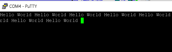
Undoubtedly, the project is working, and you are writing text back to the PC!
You can use this ASCII method to gather data for your own projects, or display messages for an operator if you have no other HMI.
For more information on the SLC-500, visit the category page.
— Ricky Bryce
Pingback: SLC-500 ASCII Read Line (ARL) - Bryce Automation