
How to add PIC Buttons in Assembly
When adding PIC Buttons in Assembly, we need to be sure to have a port setup for inputs. In this case, I’m using the 16F877A. Usually, the best port to add the buttons are to port B. This is because Port B has internal pullup resistors. The internal pullup resistors simply hold the pin in a known state when you are not pressing the button.
First you’ll need to create a valid assembly project. You can follow the tutorial on how to set up a basic project. You’ll need to create a new project, and add the configuration. Follow the step by step procedure to set up the reset vector, and interrupt vector in your program. Be sure to set the custom linker objects to point to these vectors.
Configuration for PIC Buttons in Assembly
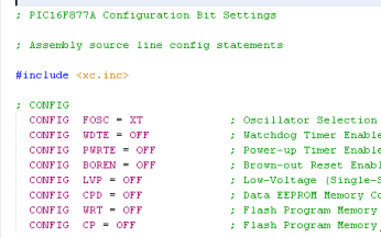
We’ll create a new project following the tutorial on how to set up a basic project. I’m creating a new source file named Startup.s. Next, we’ll set the configuration bits. In this case, I’m using a crystal oscillator, and I’ll shut off all of the other configuration bits. You will find this under Production | Set Configuration Bits. Once you generate the configuration, simply copy it into your code.
At this point, we’ll configure our vectors. We’ll enter this code into our program:
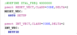
Next, we need to configure the customer linker options. Go to the properties of your project, and select the pic-as Linker
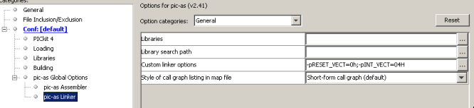
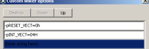
Click the ellipsis (3 dots) under Custom Linker Options. We’ll set up the RESET_VECT to start at 0h. Likewise, we’ll configure INT_VECT to start at 04h. (Note: There is no space after the -p).
Setup Routine
Next, we have a few things to set up. Keep in mind that RES_VECT will jump to the startup label. We need to have this startup label in our program, and this will effectively be the first block of code the PIC executes on startup. Remember that our configuration created an include to xc.inc. This creates labels, or aliases to memory locations to help us remember them. For example, we can simply use a STATUS label, instead of remembering the memory location of 03h.
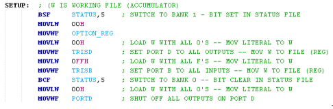
First, we’ll switch to bank 1 with the BSF STATUS,5 (Bit Clear in File) instruction. We’ll load our working file (W) with 00h using the MOVLW (Move Literal to W) instruction. Then we write this 00H to the OPTION_REG with the MOVWF (Move W to File). This enables the internal pullup resistors on PORTB. After that, we’ll load 00h to W again, and move this into TRISD. This is the tristate register for port D, and 00h will configure all the pins on PORTD to be outputs.
At this point, we’ll move 0FFH into TRISB, configuring all of the pins on this port as INPUT.
Next, we switch back to bank 0 by shutting off status bit 5 with the Bit Clear in File (BCF) Instruction.
Finally, we’ll write a 00h to PORTD to ensure all outputs are OFF before we begin.
Main Routine
At last, we are ready for the Main Routine!
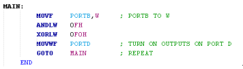
In the first instruction, we’ll move PORTB to our working register, which is W. On my setup, I only have 4 buttons. The ANDLW 0Fh (AND Literal with W) will simply look at the lower 4 bits, and set the upper 4 bits to 0. That way they are in a known state.
Next, we will set the upper 4 bits high with XORLW 0F0h. This will shut the upper LED’s off, since the outputs are also backward (0=ON). The lower 4 bits will pass though to the outputs as-is.
Finally we, use GOTO Main to create an infinite loop. Don’t forget the END statement at the end of your logic, so the assembler knows where the end of your code is.
Summary of PIC Buttons in Assembly
In short, once you have a basic project created, you can use this as a template for other projects. In this case, I’ve used a blink program, and just modified the SETUP and MAIN code to display the status of the lights. The PIC is a RISC processor. (Reduced Instruction Set Computer). This means that you don’t have many instructions to learn. You can find the instruction set reference here.
In the future, I’ll be adding more PIC posts to the category page! Feel free to visit often for updates!
— Ricky Bryce