
Introduction to Basic ControlLogix Instructions
An easy way to learn Basic ControlLogix Instructions is to understand how to convert logic to English. Before we do this, we need to understand three basic instructions: XIC, XIO, and OTE.
The XIC (Examine if Closed, or Examine On) instruction can look at any bit anywhere in memory. If this value is a 1, then the instruction is true. The instruction will then have “Logical Continuity”. Logical continuity means that it allows the flow of logic. For example…. The XIC can look at a switch. When the switch is ON, the instruction is true. Here is the symbol for the XIC:
—-] [—- Looks for a value of 1 to be true.
The XIO (Examine if Open, or Examine Off) works the opposite. The XIO instruction can still look at any bit anywhere in memory. If this bit has the value of a 0, then the instruction is true. Then the instruction is true, it allows for logical flow. Think of this as a NOT instruction. If the XIO is looking at a switch, the switch would have to NOT be on. In other words, the switch has to be OFF for logical continuity. This instructions is commonly used with alarms conditions, or Interlocks. “For a motor to start, we have to NOT have an alarm”. Or one of the conditions to close a valve is that we have to NOT be trying to open it at the same time. Another example is if we are trying to run a drive, we have to NOT be trying to stop it at the same time. Here is the symbol for the XIO:
—-]/[—- Looks for a value of 0 to be true.
Next, we have the OTE (Output to Energize) instruction. The OTE instruction will turn a bit on or off, such as a light. The OTE instruction can turn on real-world outputs, or internal bits. Here is the symbol for the OTE instruction:
—-( )—-
Consider the following logic:
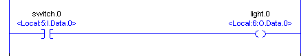
    Switch.0             Light.0
------] [------------------(  )----------
To convert this to English, we would express: If Switch.0 (is on) then (energize) Light.0. When switch.0 is turned on, a voltage will be placed on a terminal of the input module. Then, the controller tag will change to the value of 1, and the instruction for switch.0 will become true.
Examples of Logic to English
There are some basic statements that we will talk about in these English If….. Then….. Statements: AND, OR, and NOT. Imagine you are driving a car from the left to the right side of the screen. We will list the conditions that need to be made for your car to get to the output instruction on the right.
Let’s convert the following line of logic into English:
We would express this as “If switch.0, then Light.0”. For example: If the operator turns a switch on, energize a motor.
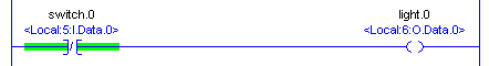
“If NOT switch.0, then light.0″ A real world example: If we don’t have an alarm, then energize a motor”
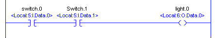
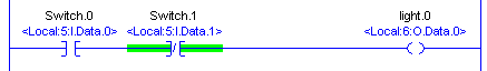
“If Switch.0 AND Switch.1, then Light.0″. A real world example: If the operator wants a valve to open AND the hydraulic pump is running, then move the valve”
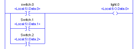
Here we have a BRANCH with a total of three BRANCH levels. “If Switch.0 OR Switch.1, OR Switch.2, then Light.0”.
Real world example: If the operator presses button to sound a warning horn on either of three panels, then energize the warning horn.
“If switch.0 AND (NOT switch.1), then light.0”. Real world example: If the operator wants a motor to run, and we do NOT have any alarms, then energize the motor.
Putting it all together
Finally, lets try another real world example that uses all of the instructions and logical functions that we have discussed so far. Here is an example with descriptions of a real line of logic with descriptions. Try this one on your own, then compare your answer with the answer below: Use the descriptions instead of the switch number for your answer.
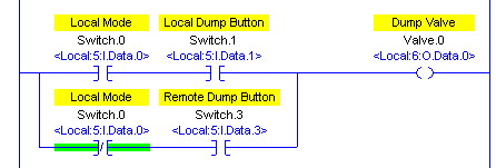
If (Local Selected AND Operator presses the local dump button) OR (Local NOT selected (meaning remote), AND the operator presses the REMOTE dump button) , then energize the dump solenoid.
Summary of Basic ControlLogix Instructions
In short, Basic ControlLogix Instructions are the fundamental building blocks of any ladder logic program. Keep in mind that the XIC (Examine On) looks for the value of 1. On the other hand, the XIO (Examine Off) Instruction looks for a value of 0 to be true. For example: We have to NOT have an alarm for a motor to start. In other words, the alarm bit needs to be off.
The OTE instruction will write to it’s tag each time it’s executed. If you have “logical continuity” to the OTE instruction, it will write a 1 to it’s tag. If the instruction is false, it will write a 0.
One misconception is that adding an AFI (Always False) instruction at the beginning of a rung disables the rung. This is not always true. Adding an AFI instruction in series with the output will cause the rung to evaluate as false. Therefore, the processor always writes a 0 to it’s tag.
To learn more, visit the ControlLogix section!
— Ricky Bryce