
Introduction to Building the Kenbak-1 Computer
In this section, we’ll be Building the Kenbak-1 Computer. This is not an original computer. In this case, we’ll build this computer using the Atmega328. This is the processor you will find in an Arduino Uno. The original Kenbak-1 computer did not have a processor. In other words, it was all transistor logic. This machine was designed by John V. Blankenbaker, and only about 50 of them were produced. At this time, I believe only about 17 of them are in existence.
Mark Wilson put together some code to emulate the Kenbak-1. You will find the code on Github. Additionally, you can purchase a kit from Chris Davis at AdwaterAndStir. The kit is much closer to the appearance of the original than the one I put together in this project. In this case, I was more concerned about the operation rather than the appearance.
If you wish to try the Kenbak-1 on an emulator, Cory Whitesell has put together an emulator that you can run right on your PC! Check out this emulator using this link.
What You Will Need for Building the Kenbak-1 Computer
Before we begin, we’ll have to gather some parts. Obviously, we’ll need 15 buttons and 15 Led’s. Additionally, we’ll need an Atmega328, two 74HC165 (Input Shift Registers), and a 74HC595 Output Shift Register. Obviously, you will need a prototype board, some wire, and a case. I’m using fifteen 10K pull down resistors, and fifteen 470 Ohm resistors for the LED’s. The schematics are in the sketch you download from Github. Simply look in the file “Pins.h”.
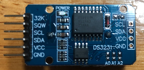
For keeping time, you will also need a clock module, such as the ZS-042 (DS3231). Be sure to change clock.h to reflect the type of module that you are using.
Keep in mind that you will need some other components for the processor to work. This includes a 16Mhz Crystal, two 22pF capacitors, and a couple 10uF capacitors.
For programming, you will need a 5 pin header, a push button for the reset circuit, and a programming device. Use an additional 10K resistor to pull up your reset pin. Another option is to place the Atmega328 into an Uno board to program it. After that, you can transfer it over to your Kenbak.
Obviously, you will need some wire to connect everything together. I always use Cat 5 solid Ethernet cable.
Set Up your Board
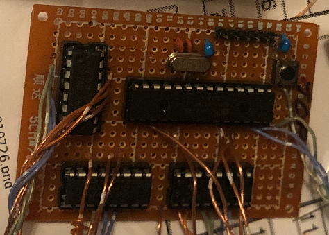
Next, I’ve added the two 165’s. Keep in mind there are two of these. I also added the 595 output register, and the Atmega328. I like to use this image for the pinout. It’s very easy to read. Keep in mind that you will need to add a crystal oscillator and 22pf capacitors for the Atmega328 to work. Additionally, be sure to add a 10uF capacitor between power and ground on the processor. It might work if you leave off the capacitor. However, from my experience, you will probably experience problems over the next few years. When the processor cycles, it causes a current draw. In turn, this will cause the voltage to drop. Obviously, this results in a “ripple” effect without this capacitor.
Remember to also leave room for the programming header and reset button if you wish to use them. I am connecting the DTR pin from the TTL programmer to RESET on the Atmega328 through another 10uF capacitor. Be sure to pull up the reset pin with a 10k resistor. When you press the button, the RES pin should connect directly to common.
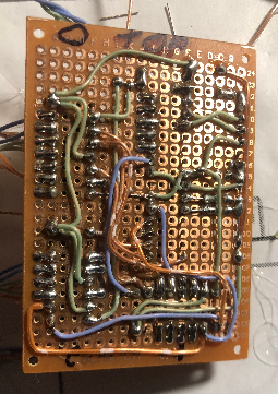
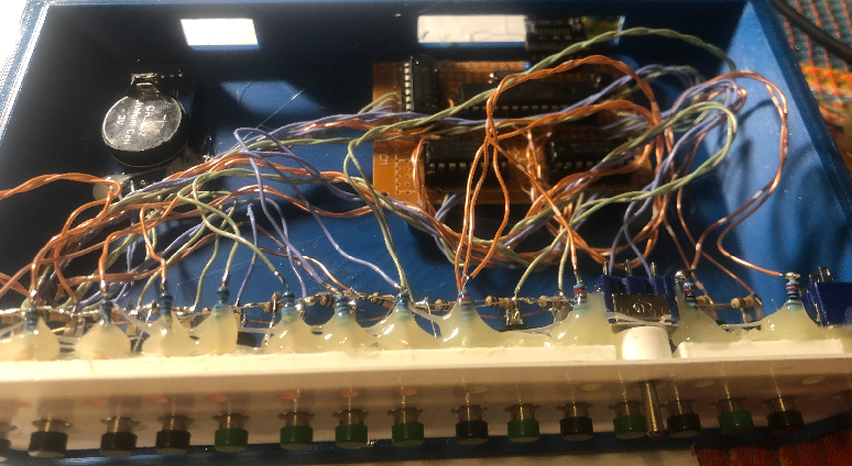
So far, this is the bottom of my board. Before soldering the sockets, you might want to put some tape over them on the top side. I used cheap sockets, so some of my pins tried to push out of it’s plastic casing on the other side. Also, be careful not to bridge connections. I’ve found the easiest way to break an accidental bridge is with a vacuum pump.
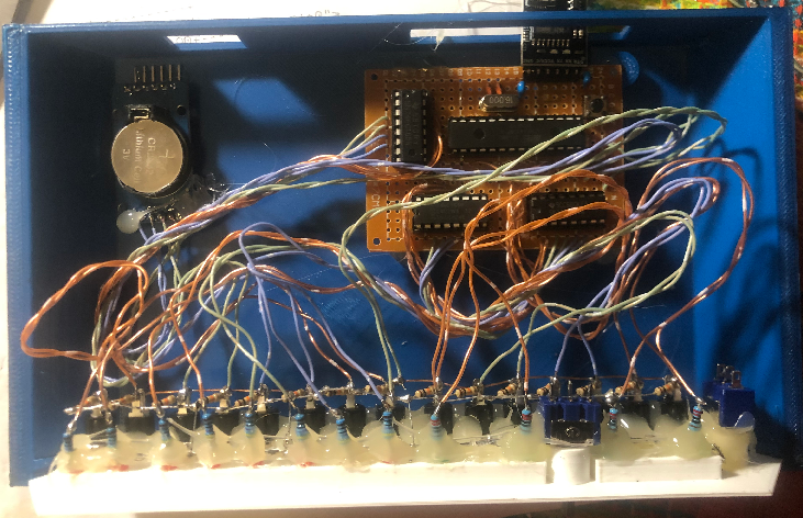
And here is the top side of it.
Front Panel Switches and LED’s
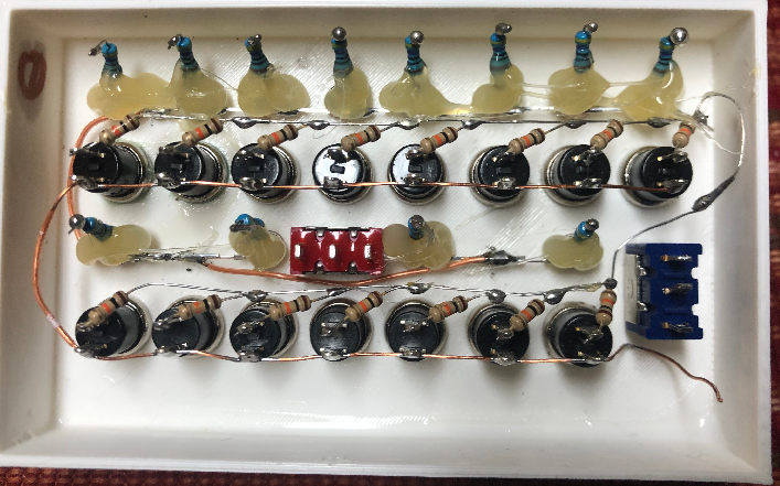
At this point, we’ll put together the front panel push buttons. Additionally, we’ll add the LED’s. Each LED has a 470 Ohm resistor in series with the long lead. At the same time, we’ll add the resistors for the buttons. I’m using a 10K pull down resistor on each push button.
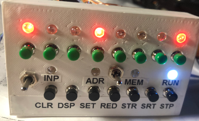
I’ve also added a power switch and a lock/unlock switch for future use. I simply printed the cover on a 3D printer. Notice this is not the exact layout of the Kenbak-1. I needed this to be compact. Since I didn’t want to take up room on my PCB, I just used hot glue to support the resistors to limit movement. If they wiggle back and forth too much, you will break the conductors.
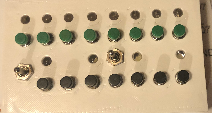
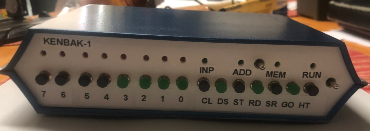
This is the front of the Panel.
Make your Connections for Building the Kenbak-1 Computer
At this point, you are ready to connect almost everything together. Simply use Pins.h for the wiring diagram. This is in the Kenbakuino download. You don’t want the wires to be so short that they won’t reach. On the other hand, you don’t want them to be so long that you cannot fit them in the box. If you get the order of the lights or switches incorrect, you can change the program before you download. In this case, I got the order of the LED’s backwards somehow. I just went into “LEDS.CPP” and changed LSBFirst to MSBFirst in the shift logic Later on, I’ll figure out how I got this wrong. The mapping for the buttons is in the “PINS.CPP” file
Connect the Clock Module
In this case, I used a ZS-042 module. This has the DS3231 chip. I did not have a rechargeable battery to use on this module. Because I only had a standard CR2032 battery, I had to disable the charging circuit. To disable the charging circuit, I simply removed the diode in the upper right hand corner. You will see in this image that I already have it removed. This is just above the “SCL” Label.
Test Your Work after Building the Kenbak-1 Computer
Now comes the real test. Be sure you don’t have any clippings in your circuitry. Also check to ensure you don’t have any short circuits. Power up the Kenbak-1. You should see a test pattern of lights. Hold Stop, and hit Switch 0. Hit RUN, and you should see a binary counter running.
Other Programs
In addition to the built in programs, you can send code to the Kenbak. That way, you don’t have to enter the code manually from the front panel. To send a project to the Kenbak at 4800 baud, for example, stop the Kenbak. Hold down switch 0, then press SET. After that, you can send a project’s code through a terminal emulator. You can do this from the Arduino’s serial monitor as well. You will find some projects that other users write in a uKenbak Forum.
Likewise, the Kenbak can write it’s program to your terminal. Simply stop the Kenbak. Hold switch 0 (for 4800 baud), then press “Display”.
Holding other switches (1, 2, or 3) will set the Kenbak to different baud rates. For reliability, though, I just use 4800 baud. With the limited memory of the Kenbak, you won’t be waiting long for a program transfer.
Programs
The following programs are built in to the code:
- 0 – Binary Counter
- 1 – Cylon (like Knight Rider)
- 2 – Clock (Count the Bits)
- 3 – Clock (In BCD Format)
- 4 – Clock (In Binary Format)
- 5 – Blinking Lights
- 6 – Find Primary Numbers
- 7- Set the Clock
Execute the built in programs:
- To run a built in program press STOP + the bit number of a built-in program that you wish to run. Press Start.
- To run a program at power-up, unplug your unit. Press STOP + bit number of the program. While holding down these buttons, apply power.
- If you wish to change the speed of the processor, press stop. Then press a bit number + stop again. The higher the bit number, the slower the processor runs.
- To set the clock, press Stop + Bit 7. Press Clear then Set. Enter the hours in BCD Format. Press STORE. At this point, enter the minutes in BCD Format. Press STORE again. After that, press RUN. Your clock should now be set. Press STOP and bit 3 at the same time to run the BCD Clock Program.
Summary
To Summarize, this is a fairly easy build. Simply mount your components onto the PC Board. Follow PINS.H for the schematic. There are several built in programs. To run these programs, just hit stop, then a data button.
Update — March 26, 2022
I found the project that Michael Gardi put together here. He’s got a nice case in .STL format that you can download and print out. The only problem I had with this case was the side rails, so I had to improvise. This was just due to the low resolution of my printer. It might also be my print settings.
As you can see, I did keep the Atmega328. The project at the above link actually uses a Raspberry Pi.
The appearance is much closer to the original than the first unit I put together. It’s just 2/5 scale. Also, I did not have a good way to add a faceplate, so I just used labels. Some of them need to be straightened a bit.
For other similar projects, visit the Arduino Intermediate Page!
— Ricky Bryce