
Building an I/O Module for the Southern Cross
In this section, we’ll be Building an I/O Module for the Southern Cross Computer. The Southern Cross Computer is a Z80 system designed and maintained by Craig Jones. This system is useful for recreational and educational purposes. With this machine, you will learn about assembly programming on the Z80 processor. Grant Searle also has a BASIC ROM that works on the Southern Cross. Retro Phil has also set up a version that contains a monitor.
The Southern Cross has an I/O port that is useful for building your own projects. This port already decodes addresses 80H to 83H. The port also has pins for power, and reset.
We’ll be utilizing all of the Pins on the I/O port to build a module for inputs, and outputs. You can design these as separate modules, or build the I/O all into one module. In this example, we’ll use the ports 80H for output. Likewise, we’ll use 81H for input.
Setting up the Output Module
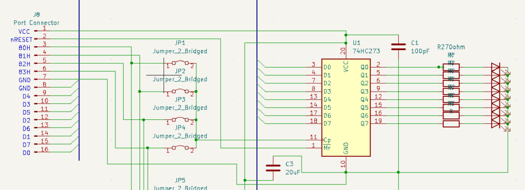
First, we’ll take a look at how to connect an output module. For this, we’ll use a 74HC273. Basically, on the connection header, you will connect D0-D7 on your port to D0-D7 on the 74HC273. Obviously, you will need to power the IC. I would also recommend a 10uF capacitor between VCC and GND. Additionally, I always like to put a bypass capacitor of 100nF between VCC and GND. (code 104). Additionally, you can connect the reset pin of the port (pin 2) to reset on the 74hc273. That way, you wont be holding random LED’s on at startup.
Each of the Q pins will connect to a different LED through a resistor. The value of this resistor depends on the tolerance of your LED’s, and how bright you want the LEDs to be. In this case, I’m just using a 270 ohm resistor in series with the LED’s.
You will also need a way to address the port, which connects to your clock pin of the 74HC273. I would recommend setting up a header, where you can select which ports you wish for the outputs to run on.
Here is a schematic. This is my first attempt to put a KICAD schematic together, so everything is not perfect, but it will give you a good idea of how I set mine up. C1 should be 100nF (capacitor code 104).
Setting up the Input Module
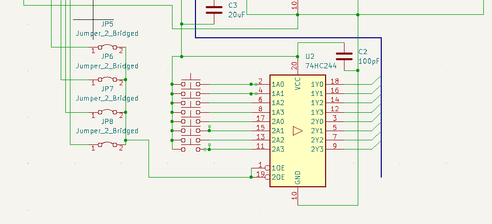
At this time, we’ll discuss the input module. Obviously, we will connect this to the port header as well. We’ll connect D0-D7 to the “Y” pins on the 74HC244. Likewise, all of the “A” pins will connect to switches. I did not add the pull down resistors on this schematic, but you might want to add a 10k pulldown resistor to the 74HC244 side of each button (I’m trying to keep the diagrams small and legible). If you use dual throw switches, you can simply connect one thow to VCC, and the other to GND.
Keep in mind, that it’s a good idea to have a 10uF capacitor on this IC, and also a 100nF as close to the IC as possible. This acts as a bypass capacitor to filter unwanted ripple from voltage drops in the line as the IC goes through cycles. In my case, I just added a 20uF capacitor for both IC’s, and then placed a bypass capacitor on each one.
As I said before, it’s a good idea to have a header to select which port you wish your inputs to run on.
Keep in mind that if you use buttons, you will want to hold them to a known state when the button is open.
(Note: C2 should be 100nF… Capacitor code 104.)
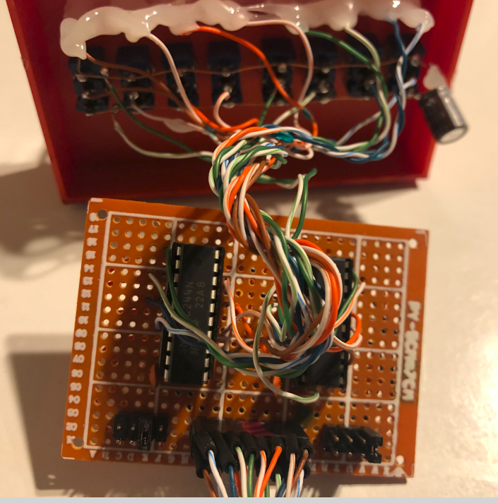
Putting it All Together
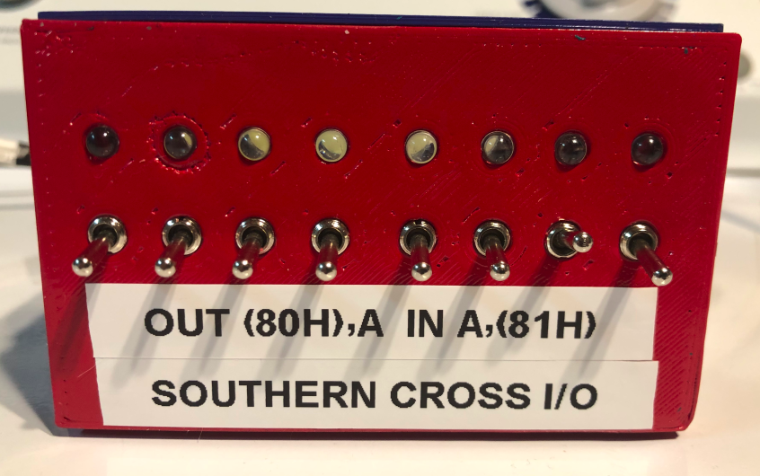
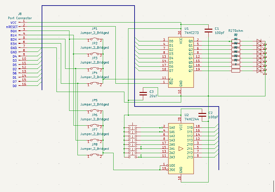
Here is the entire schematic, and how I set this up on prototype board.
Programming the I/O Module for the Southern Cross
You can use the I/O Module in assembly, or in BASIC. If you use assembly, simply use the command, OUT (80H),A to send the value of A to your LED’s. Likewise, IN A,(81H) will bring the value of the switches into A. Consult the manual for your version of BASIC to understand how to use the IN and OUT commands.
Check out my BinaryOctalHex.asm file on github for an example that uses this I/O module to display Binary on the LED display, and Octal and HEX on the 7 segment display of the Southern Cross. The switches will control the high byte of the delay loop to slow down the program.
For more information, visit the Vintage Computers Category Page!
— Ricky Bryce