
Introduction to ControlLogix Modbus
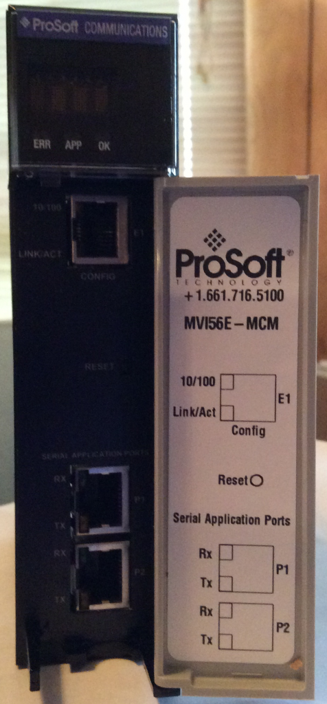
In this document, we will walk through ControlLogix Modbus examples using the 1756-MVI56E module. The MVI56E-MCM modules allows connections between the Modbus network, and a ControlLogix processor. Before using the MVI module, we will need to set up the configuration such as the IP address for the Configuration port, and the jumpers for the proper network protocol. This MVM module is capable of RS232, RS485, and RS422 protocols. This document is for example only, and the procedures, as always, must be modified for your needs.
For this exercise, we will be setting up the jumpers for RS232, so we will be limited to a point-point connection, and a distance of 50’.
If multiple devices are required, RS422 or RS485 can be used, and the cable is limited to 4000’, and typically limited to 32 nodes. Termination resistors of 120 Ohms (½ Watt should be used to terminate both ends of the network.)
The module has several status lights to indicate the state of operation.
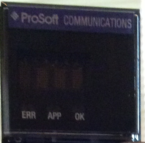
An alpha-numeric display will scroll information such as the IP address, the modes of each port, and the status of the module. In addition to this display, there are 5 other types of status indicators:
A) ERR – This is the battery status. The internal battery should last the life of the module.
B) APP – Application Status. This indicates when the program has configured the module.
C) OK – This indicates the status of the module, and should be solid green. If the module is solid red, an error has been encountered in the program, or a hardware fault has occurred.
D) The Ethernet status lights will indicate when a connection is made, and data is being transferred
E) PRT1 and PRT2 indicates the status of the modbus ports.
Configure the Module
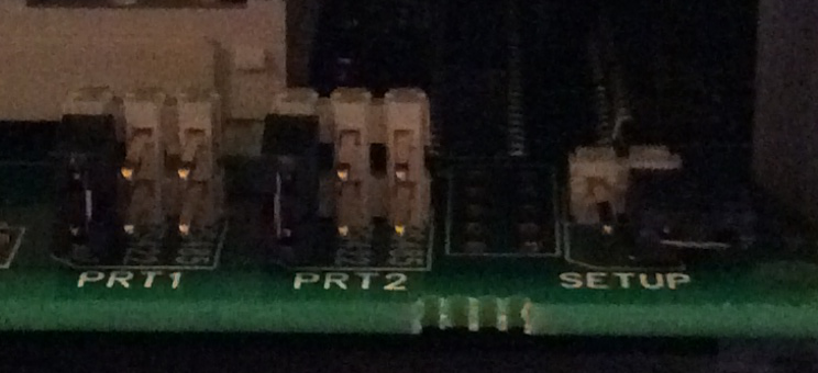
1) Set the jumpers on the module to RS232 for port 1 and port 2 Ensure the setup jumper is in the OFF position. This will prevent the firmware from being changed on the module.
2) Place the module into the chassis, and power up your work station. You will notice the OK indicator is solid green, and the APP indicator is off. This indicates the module has not been configured yet from the program in the processor.
Configuration Builder (Optional for this module)
Skip to step 16 if you are not interested in the utilities on the module itself.
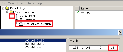
3) Connect an Ethernet cable to the Modbus interface. Notice the default IP address is 192.168.0.250. This will need to be changed because we cannot have more than one device on the network with the same IP address.
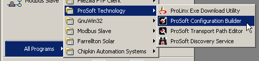
4) Open Prosoft configuration builder.
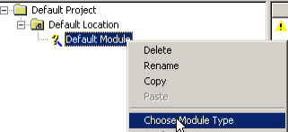
5) Right-click the default module, and choose the module type.
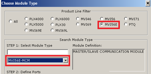
6) Select MVI56E, and then choose the MVI56E-MCM module. Then press OK.
7) Under Ethernet Configuration, enter the IP address for our module, then press OK.
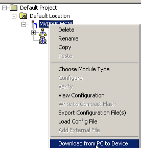
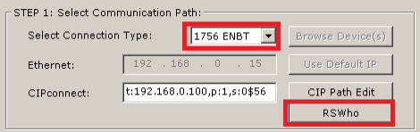
8) Download your settings to the module. We will do this through the ENBT module in the chassis. Right click the module itself, and download from PC to device.
9) Chose the ENBT module, and then click RSWHO. (The Ethernet driver for the ENBT module must first be configured in RSLinx)
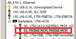
10) Browse to your MCM module, then press OK.
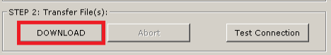
11) Now, click Download….
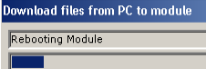
12) A progress bar will display the progress of your download, and the module will reboot.
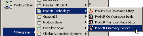
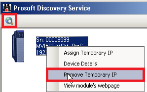
13) Now, we will remove the temporary IP address. Open the Prosoft discovery tool. You can download this from the Prosoft website.
14) Browse for the module, then right click the module, and choose “Remove Temporary IP address”
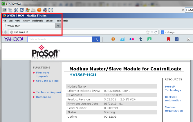
15) Now you can bring up the web page for the module by typing the IP address into the browser’s address bar.
EDS — Electronic Data Sheet
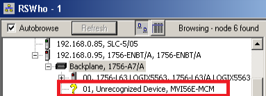
16) Next, we will run the EDS wizard to import the Electronic Data Sheet for the module. The Electronic Data Sheet provides information about the module to RSLinx. If the Icon of a question mark “?” appears on the module when browsing for the module across the ControlLogix backplane, then the EDS file has probably not been imported yet.
If the EDS File for this module is located in the module itself, you should be able to right-click the module, and upload the EDS file from the module, but if this does not work, we can download the EDS file from the manuafacturer.
Note: At the time of this document the URL to download the EDS, Sample ladders, and Add-On rungs is located at:
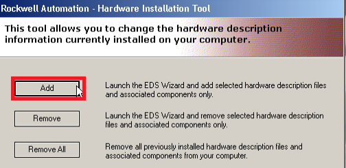
17) To run the EDS Wizard, go to Start | All Programs | Rockwell Software | RSLinx | Tools | and run the EDS Hardware Installation tool.
18) We will be adding a device:
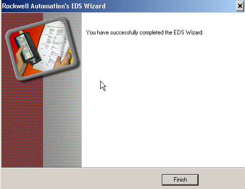
19) Register a single file, then brows for the EDS file that you downloaded from the manufacturer. Then click Next.
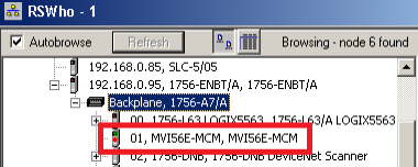
21) Now we will verify that RSLinx is viewing the module properly, by browsing across the backplane of your ControlLogix chassis using RSWHO.
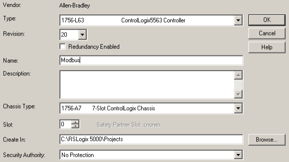
22) Next, launch RSLogix 5000, and create a new project. For our classroom example, we will just name the L63 controller “Modbus”, we have a 7 slot chassis, and the Controller is in Slot 0. we are using version 20. Press OK.
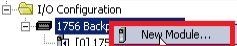
23) Now we must add our MVi56E-MCM module to the backplane. Right-click the backplane in the I/O Configuration tree and select “New Module”.
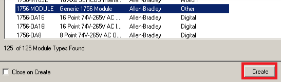
24) Because this is not an Allen-Bradley module, we will choose a generic module. This will be “1756-MODULE”, then create a connection to this module.
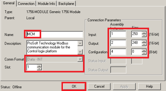
25) The documentation from the manufacturer tells us how to populate the fields for this module for proper operation. Please press OK when finished.
26) Be sure to extract the sample ladders that we downloaded earlier. This will contain the Add-On rungs as well.
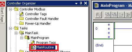
27) Next, we must import the Add-On Rungs. These will be the rungs that pass data too and from the module, and allow the module to be configured for proper operation. First, we will open the MainRoutine. This is located in the MainProgram in the MainTask.
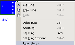
28) Now we’ll right click the margin of rung #0 (on the rung number), and choose to import rungs.
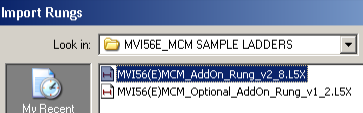
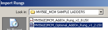
29) Browse to the folder we extracted earlier that contains the sample logic, and the add-on rungs. Import the mandatory add-on rung first (non-optional).
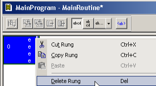
30) Press OK on the next screen, and the Add-On rung will appear in the main routine. We will need to remove the extra rung. To do this, right-click the rung number (#0) to delete.
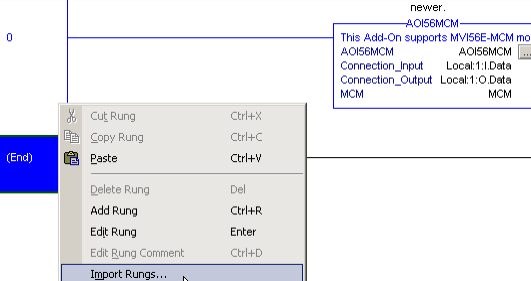
31) Next we will import the optional add-on rung to provide full functionality (for the Ethernet port, and clock configuration) Right click the end rung, and choose “Import Rungs”.
32) Browse to the folder we extracted earlier, and choose the optional add-on rung, then click “Import”.
33) Click “OK”, and you will see that both rungs are now imported. This also created, two Add-On instructions, tags, and the datatypes needed by the module.

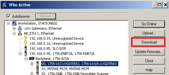
34) Now, we will download the project to your processor. Click Communication | Who Active, select the path to your processor, and choose “Download”.
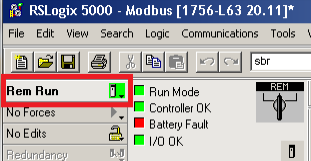
35) Place the processor into Remote Run mode.
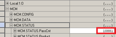
36) Next, open the tag, “MCM.STATUS”. You will see the pass count incrementing. This indicates communication has been set up to the processor across the backplane.
37) Plug the serial port of your laptop into PRT 1 of the MVI56E-MCM module. This will be a NULL MODEM cable (or a standard serial cable with Null modem adapter. You will need to use the adapter, which comes with the module to adapt the 9-pin D-Shell plug to the RJ45 port on the module.
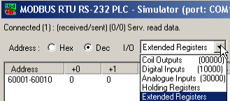
38) Open Mod_RSSIM. This software will simulate a slave device at Node 1.

39) You will notice there are 4 main types of data in a device: Discrete Inputs (Digital Inputs), Discrete Outputs (Coil Outputs), Analog Inputs, and Analog Outputs (Holding Registers). There are also Extended Registers here for extra data.
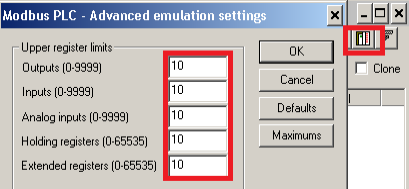
40) Under “Emulation Settings”, for the purpose of this exercise we will allow 10 each.
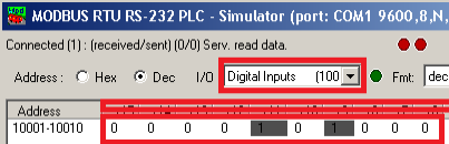
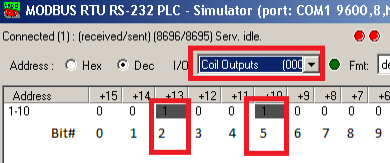
41) Under Digital Inputs, I’ve turned on two bits. Be aware that the actual address in the field device may differ from the bit number which will appear in your Controller Tag, because some vendors label the first bit as Bit #1, and Allen Bradley products start by naming the first bit as Bit #0. In this case, if we use AB numbering, I’ve energized bits 4 and 6. Since these are digital inputs, they might represent switches on a field device, or discrete status bits.
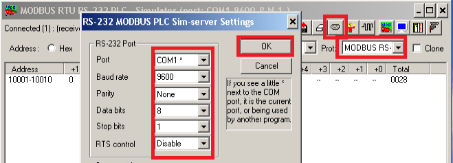
42) Next, we are ready to read these bits. Let’s check the communication parameters of our field device first. Be sure RS232 is selected on the field device, and go to the serial port configuration. Note the Communication Parameters of the device. We will need to configure Port 1 of our scanner to match these parameters (or vice-versa).
Master Configuration
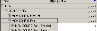
43) Now we must check the configuration of Port 1 on our MVI56E-MCM Module. In RSLogix, we will find the tag MCM.CONFIG.Port1
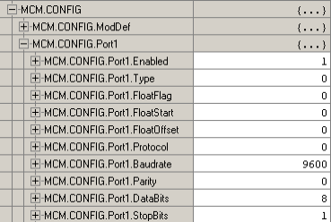
44) Now we must configure Port 1…. The most important settings for operation are as follows:
A) Enabled: 1 will enable the port…. enter 0 to disable the port.
B) Type: 0 for MASTER, 1 for SLAVE. (other settings can be found in the manual for the module such as data swapping, and pass-through.
C) Protocol: 0 for RTU mode, 1 for ASCII mode. Typically, we will use RTU (Remote Terminal Unit) RTU is a binary mode, and ASCII is a readable format)
D) Baudrate: This is the communication speed. All devices must use the same baudrate which are on the same network. Typical settings are 19,200 or 9,600.
E) Parity: 0 for none, 1 for odd, and 2 for even. Parity is the simplest form of error checking. All devices should have the same parity setting.
F) DataBits: For RTU mode, set this to 8. ASCII can be 7 or 8.
G) StopBits: Valid settings are 1 or 2 (bits that delineate a byte) Typical setting is 1.
Note: Other settings can be found in the MVI56E-MCM manual, but we will leave these at the default settings for this post.
44) When finished, our settings will appear as follows:
Reading Coils (inputs from device)
45) Now, we are ready to set up our first command. Open the controller tag “MCM.CONFIG.Port1MasterCMD[0]”.
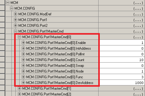
46) The command structure is as follows:
A) Enable: Set to 1 to enable the command. 0 disables the command. A value of 2 will be used for a conditional write (upon a value change in the master that is to be sent to a slave.
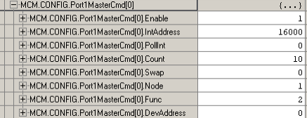
B) IntAddress: This is the memory location (in controller tags) that we will be storing data.
For bit level commands, you must define this at the bit level.
Since MCM.ReadData[0] is register 1000 in our ControlLogix, we will specify 16000 (16 bits x 1000 words).
C) Pollint: Sets the number of seconds we wait before the command is issued. We will leave this at 0.
D) Count: Sets how many words or bits to read from the device. Set this to 10
E) Swap: This is typically only used for floating point data. We will leave this at 0. The settings for swap are (each letter represents a byte (8 bits)):
0: No Swapping (ABCD)
1: Word Pairs are switched (CDAB)
2: Byes and words switched (DCBA)
3: Byes swapped (BADC)
F) Node: This is the node we are communicating with. Our slave is at Node 1
G) Func: This is the function we wish to perform for this command. We will set this to 2.
Typical functions are as follows:
1: Read Coil Statuses (discrete output status)
2; Read Input Coils (discrete input status)
3: Read Holding Registers (analog out or in)
4: Read Input Registers (analog inputs)
5: Write single coil
6: Write single register
15: Write multiple coils
16: Write multiple registers
H) DevAddress: This is the address of the device we want to read or write from. We will set ours to 0 to begin reading data from the first bit.. From left to right we will number the bits 0 to 9. We energized bits 4 and 6 (disregard the numbers in the address line)
47) When finished, our command structure should appear as follows:
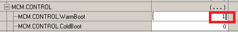
48) Next, we must warm boot the module to re-write the new command list configuration. Under the tag MCM.CONTROL, manually write a 1 onto the WarmBoot tag, then press enter. The tag will automatically toggle back to 0.

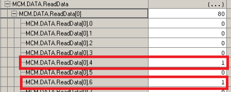
49) Now, open MCM.Data.ReadData[0], and you will see that we have successfully read the input status. (Bits 4 and 6 are high as they were in the field device)
Writing Coils
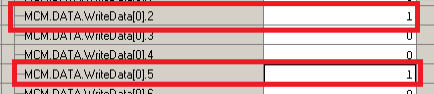
50) Next, we will attempt to write multiple coils. Open the tag MCM.Data.WriteData[0], and place the value of 1 into bits 2 and 5. This will simulate our logic calling for a field device to energize.
51) Now open MCM.Config.Port1MasterCmd[0], and configure as follows: (Refer to step 46 for function codes)
Note: If the value of enable is set to 2, then the coils will only be written when a change takes place at the source. This can reduce traffic on the modbus network.
52) Now perform a warm boot on the module again.

53) Now, back in the simulator project, you will find that bits 2 and 5 are energized as we predicted.
Reading Analog Inputs
54) Next, we will read multiple analog inputs. This will simulate a slave this is will provide analog inputs back to the processor.
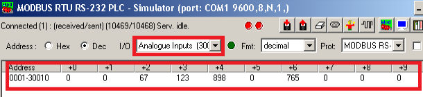
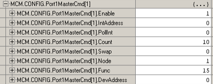
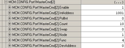
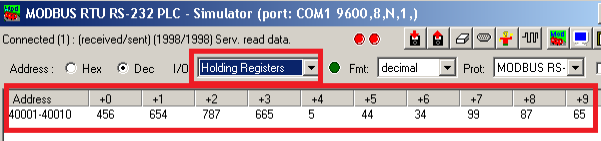
55) Set up MCM.Config.Port1MasterCmd[2] as follows. Recall that Register 1000 was already in use from reading the discrete inputs, so this time, we will map the internal address to 1001. (Refer to step 46 for function codes)
56) Now, perform a warm boot of the module again.

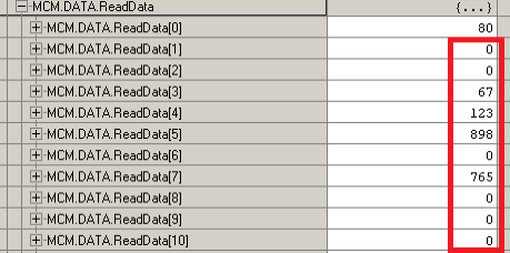
57) Open MCM.Data.ReadData, and you will see that we are getting the analog inputs from the slave device at Node 1…. Starting at Word 1 (Register 1001)
Writing Analog
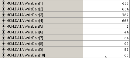
58) Now we will write analog data to the slave. Open MCM.Data.WriteData…. Populate words 1 to 10 with random values. This will simulate data coming from logic that must be written to the slave.
59) Now, we will need to configure our MCM.CONFIG.Port1MasterCmd[3] as follows: (Refer to step 46 for function does)
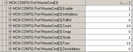
60) Again, perform a warm boot of the module.

61) You will see our data is now getting to the field device:
Working with Floating Point
Float 32 requires two 16 bit words to develop a full floating point number. For this section we will receive the floating point number, and place the data into two words. We will then copy those 2 words to a floating point tag, and this should restore our floating point number back to near-original precision.
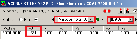
62) Let’s place our slave into floating point mode. Then we will choose “Analog inputs” and type “1.654” into the first register.
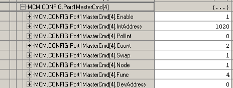
63) Next, we will set up our command structure as follows for MCM.CONFIG.Port1MasterCmd[4]. Notice that is swap code will be required because the floating point method of the device is different than the floating point method of our processor.
64) Now perform a warm boot on the module.
65) If we open MCM.Data.ReadData[20-21], we can see that this is not our original number, and it did take 32 bits to store the data.

66) Go to EditTags. We will create a tag called “MyFloat”, and the type of this tag will be “Real”.

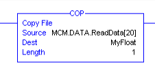
67) Next we will go back to the MainRoutine, and create a COP instruction as follows:
Note: The length is 1, because the copy instruction uses the Destination to determine how may bits to copy from the source…. Since MyFloat consumes 32 bits of memory, and a length of 1 is specified, 32 bits will be pulled from the source.
68) Now we’ll go back to Controller Tags, and in the “Monitor Tags” mode, you can see we now have or original value restored again (with slight loss of precision)

Slave Configuration
69) Now that you know now to configure the MVI56E-MCM’s Port 1 as a master, we will now configure Port 2 as a slave. First, move your cable from Port 1 to Port 2 on the module.
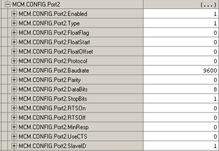
70) Open MCM.Config.Port2. Set up port 2 as follows. Note the type is 1 (slave) and the SlaveID is 1
71) Perform a warm boot of the module

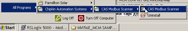
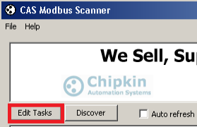
72) Open the Chipkin Modbus Scanner
73) Click “Edit Tasks”
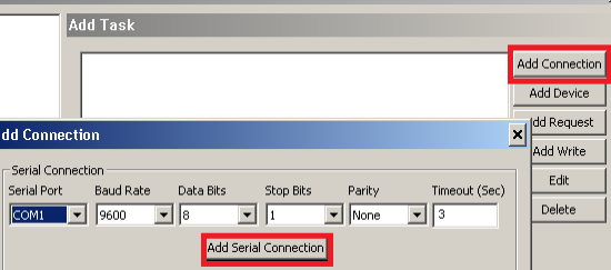
74) Next we will Click “Add Connection”. Set up the port as follows, then click “Add Serial Connection”
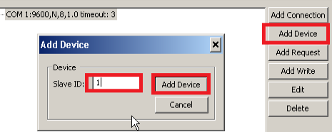
75) Next, we will add a device with the slave ID of 1
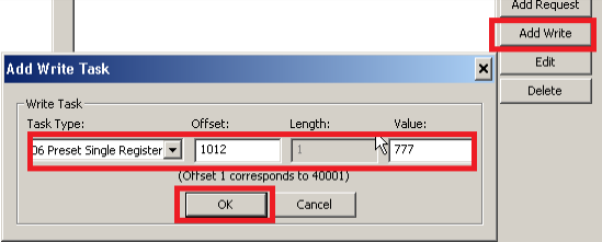
76) Next, we will add a write task. The preset will be 11, and enter the value to write to the slave.
77) Now, we will see our data is in our Controller Tag

For more information on ControlLogix, visit the Controllogix Category Page!
— Ricky Bryce