
Introduction to Inductance
We provide inductance with “coils”. You may also call them “Chokes”. The unit of inductance is a “Henry”. We know that capacitors oppose a change in voltage, but an inductor opposes a change in current flow. We use inductors to filter noise in a circuit, for tuning a radio circuit, or even to create an electro-magnet. The electromagnet can actuate devices such as a relay or motor starter.
With this in mind, there are several factors that affect the inductance of a coil. First, the number of turns affect Inductance. The more turns you have, the more inductance there will be. Secondly, the spacing of the turns affect the inductance. The closer the wires are spaced, the more lines of magnetic flux will be cut. For this reason, we will have higher value. Thirdly the number of turns is important. The more turns of wire you have in the coil, the more inductance you have. Next, is the diameter of the coil. Larger diameter coils will have a higher value than smaller diameter coils. Fourthly, is the core of the coil. If you have a core with high magnetic permeability, such as a soft iron core, you will have a higher value than with an air core.
A point often overlooked is the size, or gauge of the wire itself. All though the wire size does not make much of a difference with inductors, you might come into a limitation on the number of wraps that you can have for a given size. Finally, number of layers affect the inductance. More layers of coil wire will have a greater value.
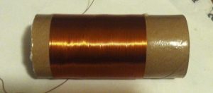
Here is an example of an inductor:
Radio Circuits
You can use inductors in radio circuits. When you use a capacitor with an inductor, they will both have a resonant frequency. We can use this resonant frequency to tune a radio. It’s important to realize the inductor itself will also have some amount of capacitance. Any time you have conductors separated by an insulator, you will have some capacitance. You may have seen a crystal radio. This is an AM radio which uses an inductor.
In World War 1, they would use this type of a radio to hear broadcasts. They simply change the resonant frequency by sanding off some of the insulation. At this point, you use a “wiper” or another piece of metal to change the amount of inductance in the circuit. A crystal, or diode acts as a detector. With a small earpiece, you don’t even need to power this type of radio. It gets it’s power from the airwaves!
Calculations for Inductors:
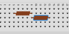
Calculating inductance in series or parallel is the same as that of a resistor. If the inductors are in series, we just add the indcutor’s values together. Let’s look at the following example where we have two 10 microhenry inductors in series. The total inductance is the sum of the two inductors. In this case, the total inductance is 20 microhenry.
Now let’s look at the same two inductors in parallel with each other.
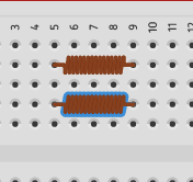
In this case, the total inductance can be found with this formula: 1/L1 + 1/L2 + 1/L3……. = 1/Lt
We would find the inductance of the parallel circuit as follows:
1/10mF + 1/10mF = 1/Lt
Therefore, 1/10 + 1/10 = 1/L1
Our common denominator is 10, so we will then have 2/10 = 1/Lt
If we invert both sides of the equation: 10/2 = L1/1 Therefore L1=5 microhenrys.
Warning! Much care needs to be used when working with inductors. When the power source is shut off, the field of the inductor collapses as it attempts to maintain a constant current. This could lead to a very high voltage being introduced into the circuit in the opposite direction of what caused the coil to energize!!! Use coils with very much care!
— Ricky Bryce