
Introduction to ControlLogix Ethernet I/O
Controllogix Ethernet I/O is inputs and outputs in another chassis (besides the local chassis) that we are reading and writing to. Remote I/O is very important for large systems. We will normally use Remote I/O if the system has more I/O than what will fit in the local chassis. Additionally, if I/O is clustered around various locations, we will mount a remote I/O chassis. This way, we don’t have to pull all of the wiring back to the cabinet where the local chassis resides. Other protocols such as ControlNet can be used. This procedure can still be followed. Just modify the catalog numbers and addresses accordingly.
Examples of devices which run on remote I/O include another ControlLogix Chassis, a Flex Chassis, an SLC chassis, a Drive, or a Panelview. The most common protocol to use with ControlLogix for remote I/O is Ethernet.
Ultimately, we will set up a Flex chassis (1794 series) on an Ethernet/IP network. The procedure for other chassis will be very similar.
Three Steps
There are three steps to configuring remote I/O. Let’s look at the path:
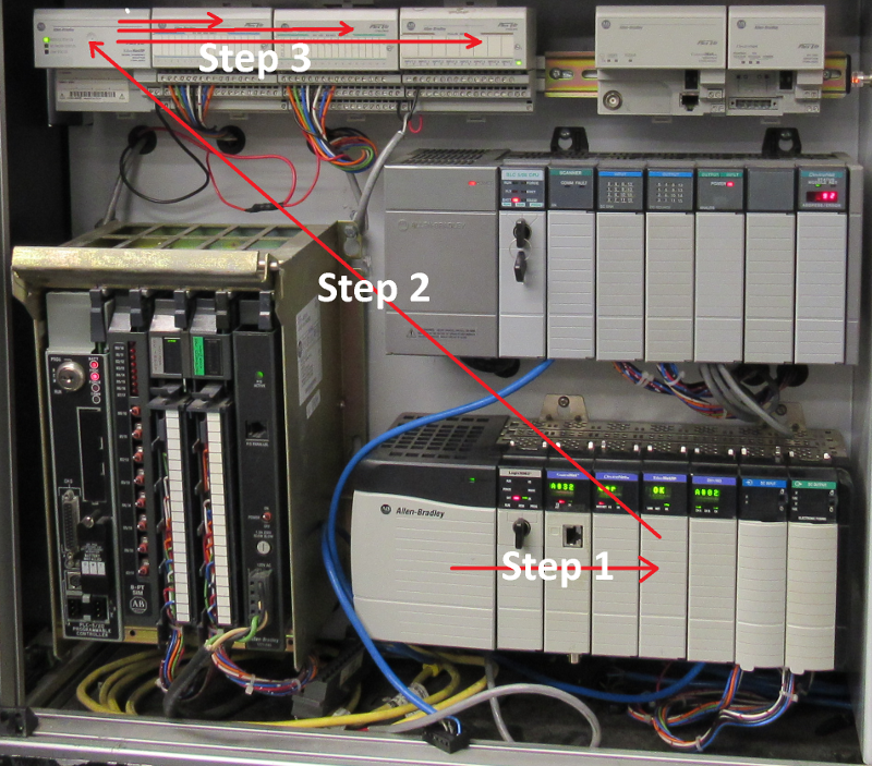
Be sure both the ENBT (or EN2T), and the 1794-AENT have IP addresses assigned, and are plugged into an Ethernet Switch. If this IP has not been assigned yet, read up on the BootP Server.
First, we will add the 1756-ENBT module to the backplane (Step 1).
Secondly, we will add the 1794-AENT module to the Ethernet Network (Step 2).
Thirdly, we will add the three I/O modules: 1794-IB16, 1794-OB16, and 1794-IE8 (Step 3).
Note: The 1756-L8x has an Ethernet port already built in. Step 1 is not required for this processor, but in most cases, you should have a separate ethernet module anyway for your Remote I/O Devices. This isolates the I/O network from your plant network for both security and performance reasons.
Gathering Information
Before we add the modules to the I/O Configuration tree, there is some basic information we need to know about each module. We will walk through gathering the information step by step.
All of the catalog numbers of the modules we are using have the catalog number labeled on them. This should not be an issue.
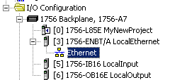
First, we need to know the slot number, IP address, and Firmware revision of the local Ethernet Module (1756-ENBT). When powered up, the IP address will scroll across the alphanumeric display. You will also need the firmware revision of this module. You will find this in the properties of the module in RSWHO (In RSLinx) if the driver is set up. Another method is to enter the IP address into your web browser if you are on the same network. The status page will show the product revision. As you can see, the Ethernet module is in Slot 3.
Secondly, we need information about the 1794-AENT module. The IP address should be written on the sticker on the module. If this is a brand new module, assign the IP address using the BootP Server. The 1794-AENT does not count as a slot number on Flex. To get the firmware revision, just enter the modules IP Address into your web browser.
Thirdly, we need some information about the 1794-IB16, 1794-OB16, and 1794 IE8. Consider these to be Slot 0, Slot 1, and Slot 2 respectively. The modules are keyed with a hardware key, so we won’t worry about the firmware revision.
This procedure is very similar for Controlnet… Just be sure you know all of the information about your modules that we will need.
Studio 5000 Configuration
Now, we’ll walk through the steps of configuring the Remote I/O in the I/O tree of Studio 5000.
Step 1
 First, we will add the 1756-ENBT to the backplane. You might be using a 1756-EN2T, newer type of Ethernet module, or even a ControlNet module. Just select the correct catalog number of your local network adapter.
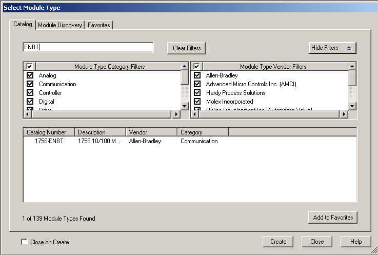
Right click the backplane and select “New Module.
Next, type ENBT to narrow your search. Choose the 1756-ENBT, and create a connection to this module.
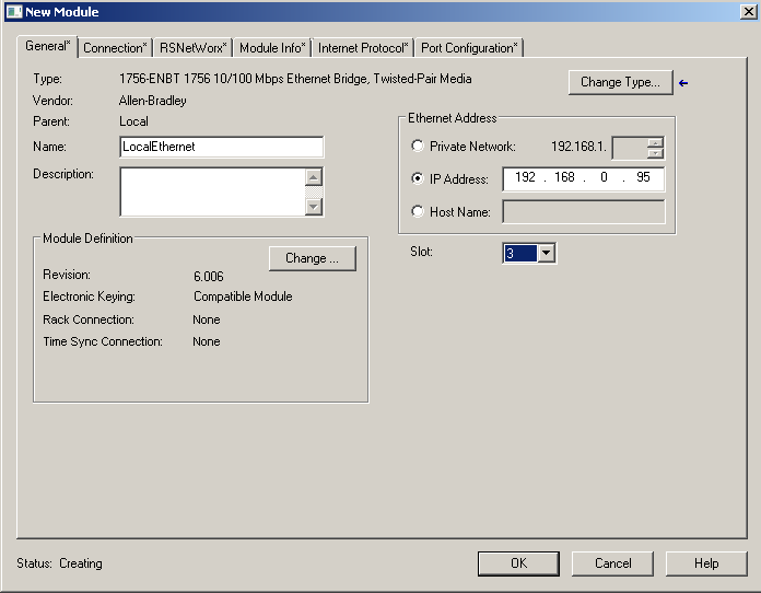
Finally, populate the name, slot number, revision, and IP address of the module. Be sure to use your own settings for your own module. Remember, this is for example only. Now, press OK.
 Step 2
 Step 2
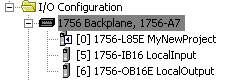
Secondly, you will see that the ENBT module is now in your I/O Configuration tree. Now, we will add the 1794 AENT to the Ethernet network. In your case, you may be connecting to another ControlLogix, Drive, Panelview, or a number of other devices. Just be sure to add the target module that you are using.
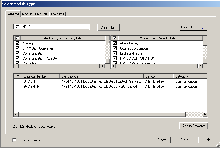
Now type in “1794-AENT” in the search box to narrow your search. Choose the target module, and press “Create”
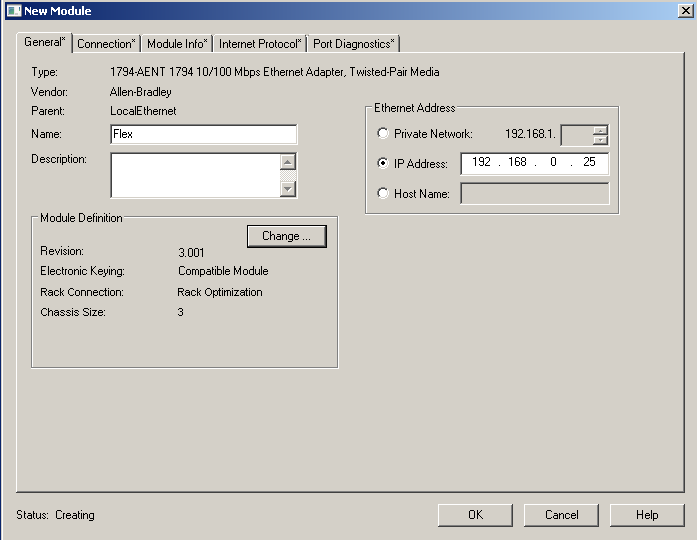
Next populate the fields as show (modifying the fields for the module that you are actually using)
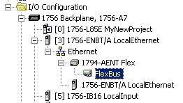
Very important!!! Whatever you name this communication adapter is what all the tag names will start with for all of the modules in the chassis. The name of the individual modules does not matter as far as tag names are concerned.
Step 3
 Step 3
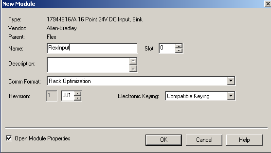
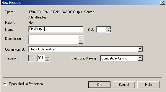
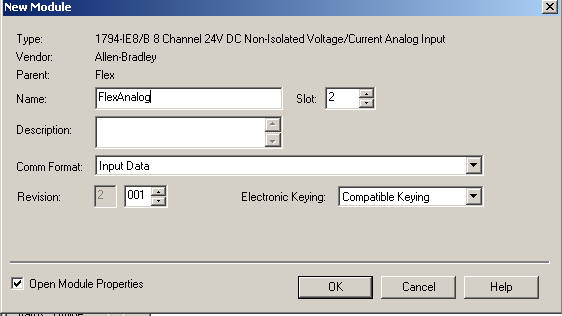
Obviously, if your field device does not have additional modules, such as a drive or panelview, you can skip this step. Now, we will add the three I/O modules to the flexbus. Right click the Flexbus (for each module) to add the 1794-IB16, 1794-OB16, and 1794-IE8. Again, this is just an example. Be sure to add the modules according to the setup that you have.
Here are snapshots of each of the I/O Configurations I used as examples on the flexbus.
First – Slot 0
Second – Slot 1
Third – Slot 2
Now, Studio 5000 has created tags for the modules on the flexbus. Next, let’s click on “Controller Tags” to view these tags.
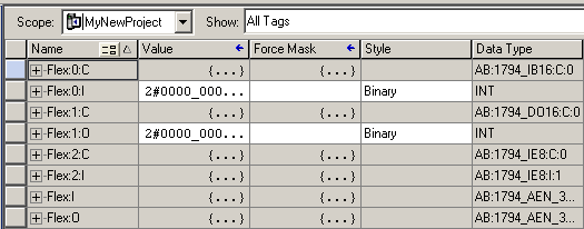
First and foremost, you will notice that all of the tags for this chassis, start with the word “Flex”
Obviously, do not confuse the Flex:I (letter i) with Flex:1 and so forth. The Flex:I and Flex:O tags exist because the controller is bundling connections. Think of Flex:I and Flex:O as status of the adapter it’self. Obviously, there is some good information here, but we are interested mostly in the slot numbers of our modules.
Finally, download your project, and open Flex:0:I. When you toggle your switches, the data table should respond.
Troubleshooting
Obviously, it is nice when everything works as planned. All things considered, though, you might have made a mistake on a module, and have an I/O light that is flashing (I/O not responding). For this reason, look for the caution icon next to any modules. Next, go to the properties of the first module that is not responding, and the error message will be on the “Connection Tab”. Finally, go back to the General tab, and ensure all fields are populated correctly.
Next, check your connections. Both Ethernet adapters should be plugged into an Ethernet Switch. Check the status lights on the switch, and the status of the adapters.
— Ricky Bryce