
Introduction to the SLC 500 Processor
The SLC 500 Processor is the main component of your SLC 500 system. The processor contains data files (which store data) and program files (which manipulate data). There are five modular processors in the SLC 500 Family (5/01 to 5/05). In this post, we will discuss the latest processor, which is the 5/05 (Ethernet processor).
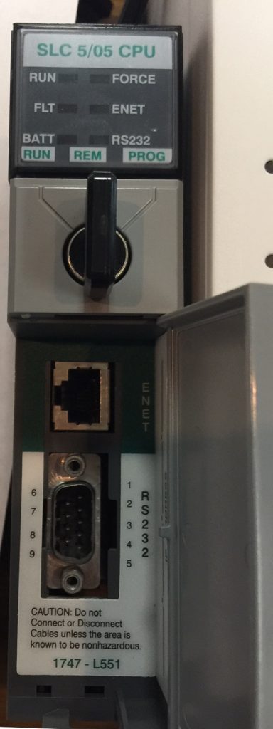
Ports
At the bottom of the processor, you will see an RS232 port. This port can be used to connect to your computer, hmi, or other processors. If you wish to connect to your PC, you will need an RS232 Null Modem Cable. For a processor with no project, this is the easiest way to download your project initially for most users.
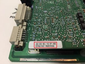
Above the RS232 Port is the Ethernet Port. In a new processor (or defaulted processor), this Ethernet port is set to obtain an IP address from a server. The Ethernet port is capable of much faster speeds than the RS232 Serial port. Using the BootP Utility, you can initially assign an IP address to the processor using the MAC ID (Ethernet Address).
The Key Switch
The Key switch consists of 3 modes, Program, Remote, and Run. When the key switch is locked into Program Mode, the logic does not execute. Online program changes require fewer steps, and therefore programming is easier. Your system will likely shut down, though, if you switch to program mode.
In Run Mode, the system is running (unless the processor faults). You cannot do online editing of your project, or download to the processor when they key is in Run. You can, however, change the values of existing data table addresses such as presets on timers and counters.
In Remote mode, you can do just about anything you need to do from RSLogix on your PC. This includes online editing, downloading, and even switching the processor between Program and Run. This is called “Remote Program” and “Remote Run” mode.
Just be aware of all possible dangers when doing online editing and changing data table values!
Status Indicators
The status indicators help us to troubleshoot the system and provide information about the state of the processor.
- BATT — The battery is low or missing. Replace the battery as soon as possible. In the SLC 5/01, or 5/02, the battery can be replaced while the system is running because the battery is located inside the front door of the processor. The 5/03, 5/04, and 5/05 must be powered down to replace the battery. The battery is located on the side of the processor. A capacitor will hold your memory for around 30 minutes as you replace the battery.
- FLT — This is the Fault Indicator. If the Fault indicator is solid red, this usually indicates a hardware problem. Flashing red indicates a software (recoverable) fault. If you have a flashing red FLT light, go online with RSLogix to determine what caused the fault. This will give you more information to correct the condition which caused the fault. Then you can clear the fault and go back to run mode. With some recoverable faults, you can turn the key between program and run to clear the fault and re-enter run mode. The problem is that if you use this method, you do not know what caused the fault.
- RUN — This simply indicates that your system is running when the indicator is solid green.
- FORCE — If flashing amber, forces are installed, but not enabled. If solid amber, installed forces are enabled.
- ENET — This is your Ethernet Status light. If solid green, the connection is working properly. Flashing green indicates packets are being transmitted. Flashing red means a fault has occurred.
- RS232 — This indicator will flicker as data goes across the RS232 port (Channel 0) when configured for DF1 mode.
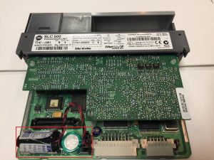
Factory Default the processor
When the battery is pulled, the processor retains the program from around 30 minutes. There are times, however, that you may want to reset the processor. For example: If you accidentally shut down the communication ports, and you need to make a change to the project.
To factory default the processor, you must first power down the chassis, and remove the processor. Next, disconnect the battery, then short VBB to GND for one minute. Finally, you can re-connect the battery, place the processor back in the chassis, and power up your system. On a processor that has been factory defaulted, your FLT light should be flashing red.
— Ricky Bryce