
Introduction to Voltage Dividers
Voltage dividers are very important to circuits monitored by microprocessors. Important to realize, microprocessors will usually handle 3.3 volts, or 5 volts. With this in mind, the voltage of the circuits they control can be much higher.
In this case, we want to measure the voltage of the 9v battery. Because the processor will only handle up to 5v, we need to reduce the voltage proportionally before we can measure it. We have to reduce the voltage because of our hardware limitations. With this in mind, once we take our reading in the processor, the answer has to be mathematically multiplied. As a result, we will store the correct voltage into a variable in the processor.
Set up the Voltage Dividers
At this point, let’s look at the voltage divider circuit.
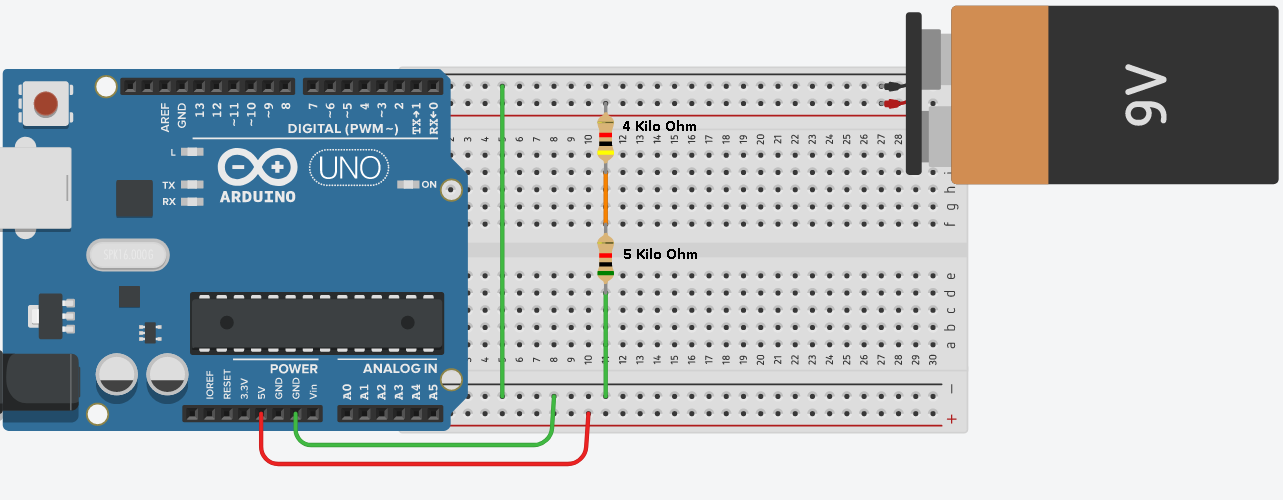
First, let’s concentrate on the two resistors.
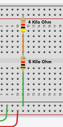
Keep in mind that we need a MAXIMUM of 5 volts to measure at the processor. At first, you might look at the circuit, and think this is easy to figure out. 5 + 4 = 9. We need a 5 volt drop to measure. Before jumping to any conclusion, let’s do the math to prove this. The reason you need to understand the math is because you won’t always be working with exact proportions of resistance.
First, let’s calculate the current. Provided that I=V/R (current equals voltage over resistance), we can conclude that I=9/9,000. Therefore current = .001 Amps, or 1 mA. Secondly, let’s calculate the voltage drop of each resistor. For the Vd of the 4K resistor, V=IR. Therefore, V=4,000*.001, or 4 volts.
Secondly, there are two ways to calculate the voltage drop of the second resistance. We know that the sum of the voltage drops across the resistors much equal 9v. Since we’ve already dropped 4 volts, we know the second resistor must drop the other 5 volts. Let’s prove this with Ohms law as well. V=5,000 ohms * .001 mA. We see the voltage drop is 5 volts.
Finally, let’s take a measurement to prove that we have a 5v drop across the second resistor.
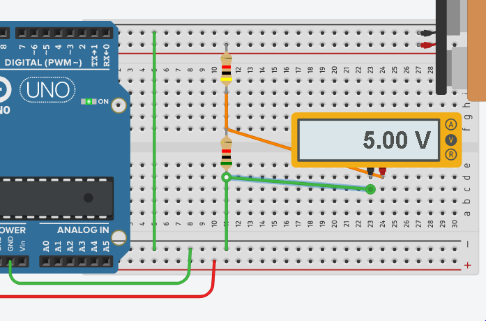
Lastly, it’s now safe to connect this point to the analog input of our processor. We know that we are not exceeding 5 volts across this resistor (as long as the 9v battery does not exceed 9v).
Potentiometers
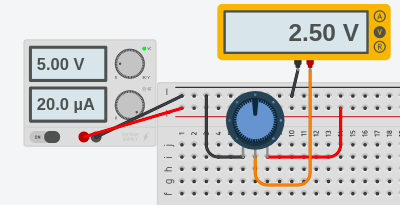
Potentiometers are also a type of a voltage divider. Internally, you have a resistor. The wiper moves along that resistor to take the voltage at different points. For example, when the wiper is all the way against the left, it’s very close to ground potential. On the other hand, when the wiper is all the way against the right, it’s a full potential. If you turn the wiper to the center, there is basically the same amount of resistance on each side of the wiper. Therefore, the wiper is at half of the full voltage. Here’s a diagram I put together on tinkercad.
Scaling for Voltage Dividers
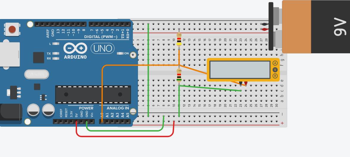
At last, the circuit is finished. Keep in mind that the analog input of the arduino has a raw value of 0-1023. In other words, when we have the value of 1023 on A0, we know that we have 5 volts. Important to realize, the value of 1023 must be “Scaled”. back into volts. Keep in mind that when we have 5 volts on A0, this means that we have a true 9 volts on the battery (because of the divider). Therefore the value of 1023 really means that our battery is putting out 9 volts.
Therefore to get the voltage of the battery, we must take the value of A0 * 9 / 1023 to get the voltage of the battery.
Powering Loads
It’s important to realize that voltage dividers are good for high impedance inputs. This includes a simple discrete input, or TTL Communication. Additionally, you can use them for analog signals. Please do not use voltage dividers to power variable loads, such as the Arduino processor. As soon as you place a load on a voltage divider circuit, the resistance drops. This causes more current to flow through one of your resistors. Once this happens, the resistor will drop much more voltage. For loads such as the Arduino processor, it’s better to use a voltage regulator, such as the 7805, or a buck converter.
For other important posts, visit the beginner’s category page!
— Ricky Bryce
Does the red wire from the arduino 5v output going to the + rail on the board with nothing else attached serve some purpose?
Good catch! I didn’t need the bottom red wire on those photos, but drew it out of habit for other I/O that might be used on the board in the future. Thanks for the comment! — Ricky