
Introduction to the Kenbak-1 Front Panel Interface
The Kenbak-1 Front Panel Interface allows us to input and view data to and from memory locations in the Kenbak-1 In this section, we’ll cover each of the front panel buttons as well as the indicator lights.
In this post, I’ll cover the use of the Kenbakuino. You can order a uKenbak-1 from adwaterandstir.com. Another option is to build your own!
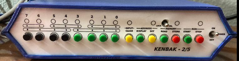
Switches 0-7
The switches 0-7 have several purposes. First, they allow you to select an address if you wish to change the value of a memory cell. When you stop the processor, the lights indicate the status of register 377. This is the register that effectively indicates which buttons you press. The clear button will reset register 377. Once you select an address, simply press “Set”. After that, you can press clear, then enter the data to go into a memory cell. Once you enter your data, simply press “Store” to change the value of a memory cell. Additionally, during runtime, you can use the buttons as user input to your project.
Lights 0-7
While running, these lights show the status of the output cell, which is 200. On a real Kenbak-1, these LED’s also show which button you are pressing during runtime (while 200 becomes dim). On the other hand, when you stop the Kenbak, these indicators serve multiple purposes. They will display the address or memory data of a cell, or show what address or memory data you are entering.
Control Buttons (Processor Stopped)
Clear Button
As I said before, “Clear” resets address 377, which represents which buttons you press. Once you select an address, or data for an address, you will typically press the “Clear” button. This will zero address 377 while your processor is not running, and all of the indicator lights (0-7) will shut off.
Display Button
When the processor stops, the display button will show the address of the current cell on LED’s 0-7. The address LED illuminates.
Set Button
With the set button, you can go to the address of a memory cell. You might do this to start viewing data, or changing data at this cell. Usually to do this, you would stop the processor, then press the clear button. At this point, enter the address you wish to go to, then press “SET”.
Read Button
Once you arrive at a memory location withe the SET button, you can read the data at this memory location. The data of a memory location will appear on the LED’s (0-7). The memory LED illuminates.
Store Button
With memory protection off, you can overwrite data at any memory location. Just be sure you are at the correct memory location, and enter the new data for that cell. Press Store. Your data will overwrite existing data. The store button is destructive. When you press this button, the run LED will flash quickly to acknowledge your key press.
Start / Stop Buttons
These buttons will start and stop the processor. When you press start, the processor will begin executing code at the location of the program counter. This program counter is in cell 003. On the other hand, the STOP button stops execution of the program. At this point you can view or change data in the Kenbak’s memory.
Memory Protect Switch
If you use this switch, it will protect the memory in the processor. In other words, you cannot use the store button to overwrite data in memory cells. While your program the Kenbak, you will want the memory protect switch off. Not all emulation devices use this switch.
Power Switch
We use this switch to power up the Kenbak-1 unit.
Control Lights on the Kenbak-1 Front Panel Interface
Basically, the control lights acknowledge your control button presses.
Input Light
The Input light comes on when your Kenbak is ready to receive input data thought the panel switches 0-7. Additionally, as you press these buttons, the input light will flash. This flash acknowledges that the Kenbak-1 is registering your key press.
Address Light
When this light is on, you are looking at an address on the panel lights 0-7. Obviously the purpose of this light is to tell you that you are looking at an actual address vs. the data at that address.
Memory Light
Similarly, like the address light, this light tells you that you are looking at data at a memory location. Again, this is to differentiate between address information and data at a memory location.
Run Light
This light tells you when the processor is running the program. Additionally, if you are entering data, this light will flicker to acknowledge a STORE operation.
Summary
In short, the purpose of this post is to provide support and reserve information about these vintage systems. It’s important for information in these posts to be as accurate as possible. If you know of corrections, clarifications, or additional information, please post in the comments section below.