
Introduction to ControlLogix Output Modules
ControlLogix Output modules control equipment. Examples of devices we attach to output modules are solenoids, lights, and motor starters. When the ControlLogix project calls for an output to energize, the status indicator on the module will light. If everything works as it should, a voltage will be applied to the device that we are controlling.
Discrete (digital) output modules, will turn on or turn off a field device. Analog output modules will provide a range of voltage or current to control a field device. The typical output from an analog card is 0 to 10 volts or 4 to 20 MilliAmps. This signal will then control the speed of a drive, or the position of a valve.
Types of modules
There are various types of discrete output modules. Examples include low voltage DC (such as 24v), or 120 Volts AC. You can purchase the relay modules, or solid state modules. The advantage of relay modules is that they have a dry contact that is open or shut. The disadvantage of relay output modules is that they are mechanical, and will eventually fail. The advantage of solid state modules is that there are no mechanical parts to fail (although they are not immune to failure). The disadvantage of solid state modules are they they will leak a little current. This means that a high impedance output (such as a neon light) will be on all of the time.
Status Indicators
The status indicators tell us that the program is calling for the output (Logic is true, or bit is forced). This does not mean the field device necessarily came on. If a field device will not energize, and the processor is calling for the output, then we usually just need to get out our schematic, and trace the problem down in the field. If the status light is not on, and we think it should be on, then we look at the program. We can find the output in logic, and navigate the logic to find the reason the output did not energize.
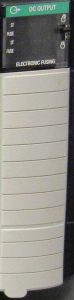
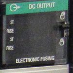
You may have other status indicators, such as a fuse indicator and an OK light. If the OK light is solid green, the module is actively communicating with the processor. If the OK light is solid red, this is an indication of a hardware failure.
Be aware that you can set the properties of the output module to energize an output, hold the last state, or shut off if the processor goes to program mode, or has a fault. This can be useful for an alarm if your process stops running, but watch for dangers of an output energizing under these conditions.
Inductive Loads
If you have an inductive load, such as a motor starter or solenoid, you should place a suppression device across it’s coil. Inductive loads can cause voltage spikes when they are shut off. This is due to the magnetic field collapsing when the coil looses voltage. We don’t want this to damage our output module.
Removable Terminal Block (RTB)
Just like on the Input module, the output module has a removable terminal block. To remove the terminal block, be sure to unlock the tab at the top of the module on the right side. The locking tab will physically prevent the RTB from being removed, when it is in the locked position. Once you remove the terminal block, a “sleeve” will slide off the top of the RTB for easy access to the screw terminals.
You can “key” the RTB of an output module by inserting “tabs” into the RTB. This just ensures the someone does not inadvertently place the wrong terminal block onto the wrong module. Obviously, the results of this can be devastating. The processor might “think” it’s just turning on an indicator light. In reality, though, if the RTB’s are in the wrong place, that voltage could cause movement.
Summary of ControlLogix Output Modules
In short, the output card will control loads such as a solenoid, motor starter, or relay cold. This could also be a simple indicator light. Our status lights tell us when the processor calls for an output. If your status light is on, but the field device did not energize, then it’s time to get out your schematic. Trace your voltage from the output module to the field device.
Visit the ControlLogix page for other information about the ControlLogix system.
— Ricky Bryce