
Introduction to Troubleshooting a ControlLogix Output
The most common problems on a system using ControlLogix are usually field devices. Occasionally an I/O module can fail. Most of the time, however we are using RSLogix/Studio 5000 to find a failed field device. In this document, we will be troubleshooting a ControlLogix output. We will locate the output in the project. Then we will navigate through the project to find the reason why the processor is not calling for an output to energize. One reason the output might not energize is because the processor is not getting an input, such as a limit switch, or a selector switch.
Most of the time, there will be just one field device that we are not getting a signal from. In this example, however, we will have multiple field devices that are not made. This will give you a better understanding of how to navigate, and locate the I/O.
Our goal here is not to change logic or the operation of the equipment in any way, but to use Studio 500 as a tool to locate failed field devices.
Understanding the Chassis Layout
When troubleshooting a ControlLogix output, you might first locate the failed output on a schematic. Your schematic will show you what chassis the output is connected to, the slot, and the terminal. If you only have one chassis with a processor, we can always start by locating the Local controller tag. All tags for all modules where the processor resides will start with the name “Local“. Tags for modules in remote chassis will begin with the name of the adapter in that chassis.
Consider the following layout:
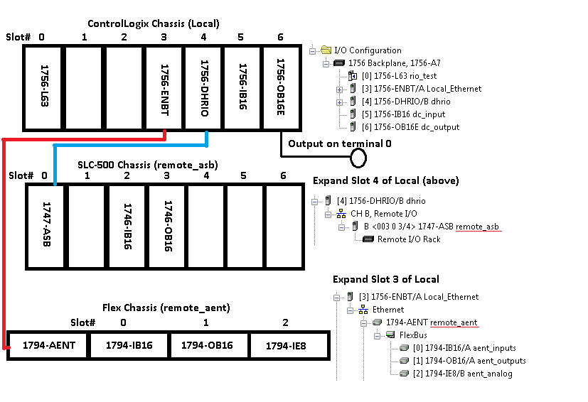
As we said before, all tags for all modules in the top chassis will begin with the name “Local“. Tags for the modules in the middle chassis will be named “remote_asb“. We can find this name by expanding the I/O tree under I/O configuration in the RSLogix/Studio 500 project. Similarly, we know that all tags for modules in the last chassis will be named “remote_aent“.
The output we will be troubleshooting in this example is shown above. This output is in the Local chassis, slot 6, terminal 0.
Locating the output in the ControlLogix project.
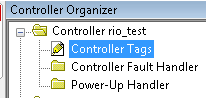
Be sure you are online with the processor. This will ensure the data that we are looking at is in real time. Next, go to Controller Tags.
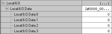
Now find the local tag for slot 6. Since this is an output module. This will be easy to decipher. We know the chassis name is Local, so find the controller tag for slot 6. We know this is an output module, so expand the Local:6:O tag. Then expand the data component of this tag.
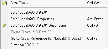
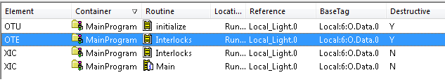
We will cross reference bit 0 of this tag to locate it’s output in logic. Right click to cross reference. You cannot left click first, or Studio 5000 will think you want to cut, copy, or paste. Right click only, and choose “Go to Cross Reference for Local:6:O.Data.0”.
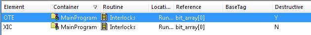
Notice the next window that opens. Usually, you will have only one instruction that is destructive. You can look in the destructive column for the “Y”. An instruction that is destructive has the ability to change the value of the tag. We want to go to this tag to find out why it’s not turning the bit on. In this case, we do have two instructions that are destructive, so we ask ourselves which one will energize the bit. The OTU (Output to Unlatch) will shut the bit off. We are wanting to turn the bit on, so we will double click the OTE (Output to Energize) instruction.
This takes us to the output in logic.
Using Bookmarks
Studio 5000 has a nice book mark system built in. However, this is normally shut off by default. To turn on the bookmarks, go to View | Toolbars at the top of your project window. Put a check mark next to “Bookmark Toolbar”.
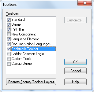
Now, you will notice “flag” icons have been added to your project. The first two icons will let you navigate between previous and next bookmarks. The middle icon (single flag) will toggle a bookmark at this location in logic. The third icon (with the x) removes all bookmarks. The last icon allows you to manage all bookmarks individually. Here, most of the icons are grey, because we don’t have any bookmarks yet.
![]()
As a rule of thumb, I will usually bookmark the first rung I come to. This way, if I get totally lost in logic, I can easily get back to the starting point, and start to navigate again. To prevent building up too many bookmarks when navigating logic, I will only bookmark a rung that has more than one condition that I need to trace down. Let’s put a bookmark on this rung by pressing the middle bookmark icon.
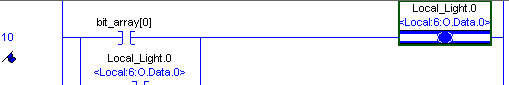
You can see the flag underneath the rung number, so we know now that this location is bookmarked.
Navigating logic
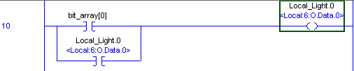
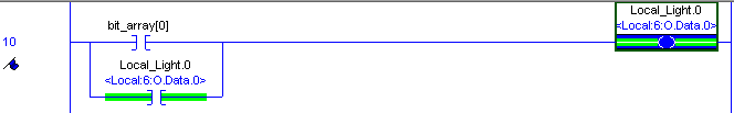
Let’s look at the conditions before Local_Light.0 You can see the alias information below this tag (Local:6:O.Data.0). You will also notice this is seal-in logic. Once bit_array[0] is true, the output will energize, and seal around bit_array[0]. When bit_array[0] goes false, the output will still remain energized. When we see a rung that seals the output, we can ignore that for now. This is because we have to take another path to get the light to energize in the first place.
We need to cross reference bit_array[0]. To cross reference this bit, be sure you are on the tag itself. You cannot cross reference an instruction, or a description. We need to right click bit_array[0], and cross reference. Then we will go to the destructive instruction.
In the following rung, we can see that bit_array[0] is not energized for two reasons. (The ONS will take care of itself). One condition is a real world input. SLC_Switch.15 is an alias to remote_asb:I.Data[1].15. If you look at the chassis layout above, we know this is on the middle chassis, slot 1, bit 15. If this was in your plant, you could locate this on your schematic to find the field device wired to this terminal. It’s possible the input is not made because a limit switch is bent or a wire is broken. Somehow, you need to get a voltage to this terminal, and then you will see the bit intensify in logic (the instruction will turn green). Once this problem is solved, we cross reference safetys[7]. This is an internal bit, and we need to go to it’s output.

Here, we see the output safetys[7] is not is not energized because warnings[31] is not made. Again this is an internal bit.

The Final Rung
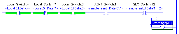
Now we can see warnings[31] output The only conditions left to fix are real world inputs now. We need to get a voltage on Slot 0 of the bottom chassis, bit 1 (remote_aent).. We also need a voltage on terminal 12, slot 1 of the SLC chassis (remote_asb). You might need your schematic and your meter, but since those are real world inputs, we need to fix them in the real world.
Once all problems have been solved, then we can go back to our bookmark (at our original starting rung). We can see the output is now energized.
Remember bit_array[0] output had the ONS instruction before it, so it was only true for one scan, however, our output stays on because of the seal.
For more information on ControlLogix, visit the ControlLogix Category page, or simply choose “ControlLogix” from the menu bar above.
–Ricky Bryce
Refer to this article https://rockwellautomation.custhelp.com/app/answers/detail/a_id/63686
Normal editing of project causes fragmentation – is it only when FBD or ST used in ControlLogix or modification in ladders also can cause this issue?
Do you have any experience?
Thanks
I have not had any problem with fragmentation, personally, but can you post an example of what is happening when you try to edit a routine? Also what version you are using. I’m trying to visualize what a problem with fragmentation might look like. I hope you are doing very well!