
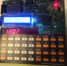
Introduction to the COSMAC CDP1802 LED Display Counter
The COSMAC CDP1802 LED Display is a six segment display on the CDP1802 Microprocessor kit. Your kit also has a place to add an LCD display as well, however, I like the appearance of the LED display. In order to use this in projects, you need to understand how to address each of the 7 segments on each digit.
For this post, I’ll be using the programming example for the LED display. I’ve used the examples in the programming book for this unit. From my location, that link seems to be down from time to time, but you can also find it on the Wayback Machine.
Digits Vs. Segments for LED Display
The display has six digits. In the programming book, we create two arrays. One array is for the digit. We simply set a bit number within a memory location to turn on a specific digit. Then we write the segment data to that digit. Keep in mind that you are just turning on one digit at a time. The idea is to scan through the digits so fast that the user does not notice.
For the digits, you will be creating six words. Each word will contain the bit number of the display you want to turn on at any given time. The codes come out to be 20H, 10H, 8, 4, 2, and 1.
We also need to write segment data to each digit. This is the hard part. We will be creating an array to store the segment data for each digit. Let’s look at one element of the segment array in detail. Remember, we just need to set particular bits to energize a certain segment of a digit.
This is not straight ASCII or or numeric data. Each bit that you set within a word turns on a specific segment.
Bit 0:  Lower Left
Bit 1:  Center Segment (horizontal)
Bit 2:  Upper Left
Bit 3:  Top Segment
Bit 4:  Top Right
Bit 5:  Lower Right
Bit 6:  Dot - Period - Decimal Point
Bit 7:  Bottom Segment

Numeric Codes (Hex data):
0 - BD
1 - 30
2 - 9B
3 - BA
4 - 36
5 - AE
6 - AF
7 - 38
8 - BF
9 - 3E
The best way I’ve found to determine the codes is to write out a 7 segment display on paper with the bit number that energizes that display. Label the top of your page from 7 to 0 for the bit numbers. Just mark a 1 on any segment you wish to energize at any given time. After that, simply convert your binary data into hex.
Program for COSMAC CDP1802 LED Display
Take a look at Program 8 in the book by Wichit Sirichote. You can use the A18 Assembler to build this project. Simply enter the code into a standard text editor (minus line numbers and object code). After you save your work, you can run the assembler to produce an Intel Hex file, which you can load (paste) directly into your unit from your terminal program.
Basically, he’s just setting up some aliases, loading some addresses, and looping through the digits. 803D is where the database starts that writes the segments. Using the chart above, you can experiment with different values for each of the 6 digits.
EF1-EF4 Checks
We can access these 4 input lines directly in the program. We’ll use EF1 and EF2 in this project. Basically, when we ground one of these pins, we know the user is pressing a button. In our program, we can check for this condition. For example, B1 will branch when the user presses EF1. On the other hand, BN1 branches when the user is not pressing EF1. BN1 $ will hold on the current line as long as EF1 is high, which means the user is not pressing the button. The logic of the wiring is negative. Program 6 in the book by Wichit Sirichote has a good program to demonstrate this. You will use B2/BN2 for EF2, and so on.
Counter Program
I’ve modified the LED Display timer, and added some logic to create a counter. Use EF1 to increment the counter. On the other hand, EF2 resets the counter. As you can see, when a user presses EF1, $8100 increments. We must then convert the value we store in 8100 to a code that represents the numeric value. We do that with the Values database. At this point, simply add the value of the counter to the address of the first element of the value database, then we get the code that represents our number we wish to display. After that, we store this code to the appropriate buffer location. The main code is always updating the display with the data in the buffers.
Once a user presses the button, Q is set. I’m using this as a flag to indicate that we’ve already taken action on the button press. The user must release the button (resetting Q), then press it before our value will increment again.
If the value of the ones place exceeds 9, then we need to reset the ones, and increment the tens place, which is at $8101.
GPIO1:      EQU 7000H
SEGMENT:    EQU 7102H
DIGIT:      EQU 7101H
ONES:       EQU 8100H
TENS:       EQU 8101H
BREAK:      EQU 2756H

    org    8000H        ;have to start somewhere ...
R0    EQU    0
R1    EQU    1
R2    EQU    2
R3    EQU    3
R4    EQU    4
R5    EQU    5
R6    EQU    6
R7    EQU    7
R8    EQU    8
R9    EQU    9
RA    EQU    10
RB    EQU    11
RC    EQU    12
RD    EQU    13
RE    EQU    14
RF    EQU    15

START:  LOAD    R3, DELAY
        LOAD    R4, SEGMENT
        LOAD    R5, DIGIT
        LDI     00H
        LOAD    RC, ONES
        LDI     00H
        STR     RC
        LOAD    RD, TENS
        LDI     00H
        STR     RD
MAIN:   LOAD    RA, BUFFER5
        LOAD    R9, VALUE0
        BR      COUNT
CONT:   LOAD    RB, SCAN_DIGIT
        LDI     6
        PLO     R8      ;LOOP COUNT
LOOP:   LDN     RB      ;GET DIGIT CONTROL
        XRI     0FFH    ;COMPLEMENT IT
        STR     R5      ;WRITE TO DIGIT
        LDN     RA      ;GET BYTE FROM BUFFER
        STR     R4      ;WRITE TO SEGMENT
        SEP     R3      ;DELAY
        LDI     0       ;TURN OFF DISPLAY
        STR     R4
        INC     RA
        INC     RB
        DEC     R8
        GLO     R8
        BNZ     LOOP    ;UNTIL 6 DIGITS
        BR      MAIN
RET_DELAY: SEP  R0
DELAY:  LDI     1
        PLO     R7
DELAY1: DEC     R7
        GLO     R7
        BNZ     DELAY1
        BR      RET_DELAY
BUFFER5:     DB 0BDH
BUFFER4:     DB 0BDH
BUFFER3:     DB 0BDH
BUFFER2:     DB 0BDH
BUFFER1:     DB 0BDH
BUFFER0:     DB 0BDH
SCAN_DIGIT: DB 20H, 10H, 8, 4, 2, 1
VALUE0:     DB 0BDH
VALUE1:     DB 030H
VALUE2:     DB 09BH
VALUE3:     DB 0BAH
VALUE4:     DB 036H
VALUE5:     DB 0AEH
VALUE6:     DB 0AFH
VALUE7:     DB 038H
VALUE8:     DB 0BFH
VALUE9:     DB 03EH


COUNT:  BQ      CHKEF
UP:     BN1     ZERO    ;INCREMENT AND STORE COUNTER
        LDN     RC
        SEX     RD
        ADD
        XRI     12H
        BZ      CONT
        LDI     01H
        SEQ
        SEX     RC
        ADD     ;INCREMENT COUNTER
        STR     RC
        XRI     0AH
        BZ      ITENS
        BR      UPDB

ZERO:   BN2     CONT
        LDI     00H
        STR     RC
        STR     RD
        STR     RE
        STR     RF
        SEQ
        BR      UPDB

ITENS:  LDI     0H
        STR     RC  ; RC NOW CONTAINS A ZERO
        SEX     RD
        LDI     01H
        ADD
        STR     RD ; RD NOW CONTAINS THE TENS VALUES
        BR      UPDB


CHKEF:  B1      CONT
        B2      CONT
        REQ
        BR      CONT


UPDB:   LOAD    R9, VALUE0
        SEX     RC
        GLO     R9
        ADD
        PLO     R9  ;R9 NOW SET TO WHERE WE NEED DATA FOR ONES
        LOAD    R6, BUFFER0
        LDN     R9
        STR     R6
UTENS:  LOAD    R9, VALUE0
        SEX     RD
        GLO     R9
        ADD
        PLO     R9  ;R9 NOW SET TO WHERE WE NEED DATA FOR TENS
        LOAD    R6, BUFFER1
        LDN     R9
        STR     R6
        BR      CONT
        END
Just modify the program to include your own preferences, then run that through the A18 Assembler to get the Intel Hex file. After that, you can upload this hex file to your kit! Here’s the hex file for the program above.
:20800000F880B3F850A3F871B4F802A4F871B5F801A5F800F881BCF800ACF8005CF881BD78
:20802000F801ADF8005DF880BAF859AAF880B9F865A9306FF880BBF85FABF806A80BFBFF62
:20804000550A54D3F800541A1B28883A3D3026D0F801A727873A53304FBDBDBDBDBDBD20E4
:208060001008040201BD309BBA36AEAF38BF3E319B3C860CEDF4FB123234F8017BECF45C39
:20808000FB0A329130A23D34F8005C5D5E5F7B30A2F8005CEDF801F45D30A2343435347A72
:2080A0003034F880B9F865A9EC89F4A9F880B6F85EA60956F880B9F865A9ED89F4A9F880C8
:0880C000B6F85DA60956303444
:0080C801B7
For more information, visit the COSMAC Category Page!
— Ricky Bryce