
Introduction to the SLC-500 Digitial Output Module
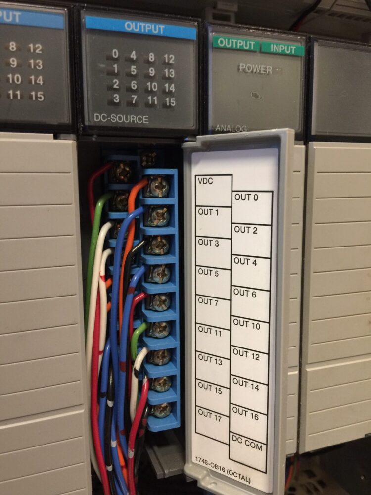
The SLC-500 Digital output module turns digital field devices on or off. Examples of these field devices include lights, solenoids, and relay coils. Think of outputs as “Control” In this example, we have a 1746-OB16 module. This module acts as 16 switches. When a power source is connected to the module, the processor “calls” for an output to energize. A switch shuts within the output module, which will energize a particular field device.
Types of digital input modules
Allen Bradley makes several types of digital input modules for various applications. For example, the 1746-OW16 is a 16 point relay output module. Some consider this to be a hard, or dry contact module. This module is good for many applications, however, a relay module will eventual fail because it is mechanical.
By comparison, other types of modules include transistor or triac controlled modules for AC or DC. Some consider these modules to be soft switches, or wet switches, and are good for applications which require many cycles. The disadvantage of the latter modules is that they leak a little current, so a minimum load is required.
All things considered, please be careful with inductive loads such as a motor starter or relay coil. When power is applied to a coil, a magnetic field builds around the coil. When power is removed from the coil, this field collapses. The field induces a high voltage into the conductor. Don’t turn your output card into a spark plug! Please use surge suppression on the inductive loads!
Replacing the SLC-500 Digital Output Module
Output modules will tend to fail more than input modules. This is because of the nature of the mechanical relays, and the potential for shorts. Short circuits place a heavy load on the modules. This is why it’s always a good idea to fuse each output individually.
To replace the module, be sure to power down the chassis, and the external power supply to the output module. Remove the terminal block from the module by loosening the screws at the top and bottom of the terminal block. Press the locking tabs on the top and bottom of the module, to pull the module from the chassis. Replace the module (with the same type of module) and the terminal block. When you power up the chassis, be sure the processor has not faulted, and the system is running.
For more information, visit the SLC-500 Category Page.
— Ricky Bryce