
Introduction to ControlLogix Input modules
ControlLogix input modules read the status of equipment. This could be any type of switch, such as a limit switch when a cylinder extends or retracts to a certain position. Inputs are also used on valves: If a valve is open or shut, a switch is made that will put a voltage on a terminal of the input module. The project in the processor can then take another action, such as starting a motor, or activating a dump table.
Discrete (digital) inputs are either on or off, while analog modules read a “range” of values. This could be a pressure transducer that measures the pressure on a pipe. Another analog input could be the speed on a motor. Flow rates are another good example of an analog input.
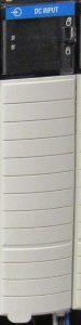
Let’s take a look at the status lights on the digital input module. Here there are two rows of status lights (barely visible in this image). The status lights indicate if a voltage is on a terminal. We connect common from an external power supply. The + side of the power supply will usually go to the switches in a system. When the switch closes, it creates a path for the voltage on a terminal.
Status Indicators
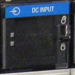
When we shut a switch, a voltage returns back to a terminal on the discrete input module. The status light will then energize. When the status light energizes, a logical 1 in the memory location for that terminal. The programmer knows what switch the terminal connects to. The programmer will then use this input in logic to know if an even has taken place on the system, such as a valve being open or shut. You will also find an OK status light. When this is solid green, the modules is active and communicating. A solid red OK light indicates a possible hardware failure in the module. On the right side of the module, you will see a locking tab. The purpose of the locking tab is to prevent the RTB (Removable Terminal Block) from coming off of the module.
Think of the input module as a group of “voltage testers”. We either have voltage to a terminal or we don’t. That is what the I/O status lights indicate.
Removable Terminal Block (RTB)
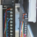
The terminal block is removable. To remove the terminal block for wiring the module, be sure the locking tab is in the unlocked position. The locking tab is at the top of the module on the right side. There is nothing electronic about this tab. It just locks the terminal block into place, so we cannot inadvertently remove it. Once the RTB (removable terminal block) has been removed from the module, a sleeve will slide off the RTB as shown. This will allow for easy access to the terminals for the purpose of wiring the module.
It’s important to realize that you can “key” the terminal blocks as well. In other words, you can put “tabs” onto the RTB. This ensures that you don’t inadvertently connect the wrong terminal block to a module. This is particularly useful when someone removes more than one RTB at a time. Putting RTBs back onto the wrong module could have disastrous results.
Summary of ControlLogix Input Modules
In short, the input module detects if voltage is present with respect to common. Status lights will indicate where we have a voltage. This is usually due to a switch in the field being shut. When a terminal has voltage, we will see a logical 1 in it’s corresponding controller tag. The programmer uses this status in the program to control your equipment.
Please visit the ControlLogix page for more posts about this system!
— Ricky Bryce