
Introduction to the Photo Resistor (LDR)
A photo resistor (LDR) will change it’s resistance based on the lighting we apply to this component. Also known as a Light Dependent Resistor, we use them in our every day life. We use photo resistors to energize night lights in our house. Furthermore, we use them in security lights, or in your automobile. This allows your vehicle to automatically energize the headlights when it’s dark outside. Here I will create a simple circuit that will energize an LED light when the room is dark.
Getting measurements
Before designing the circuit, let’s find the resistance under a lighted condition. You also need to find the resistance that we expect in a dark condition.
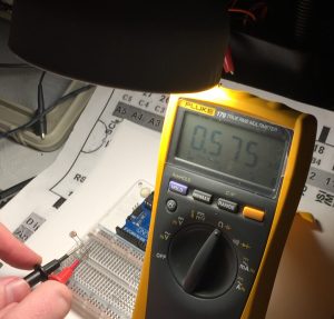
Under the Lighted condition, we have about .575 Kilo ohms.
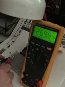
With the light shut off, we have 269.5 Kilo Ohms.
Measure the Voltage Drop
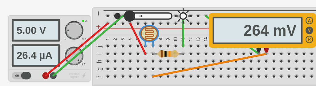
I’ve placed the LDR in series with a 10K resistor. We can easily calculate the voltage drop of the LDR during low and high intensity lighting, but let’s just run a simulation in tinkercad to see what happens.
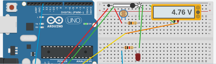
Here is our voltage drop under dark conditions. The LDR is dropping very little voltage:
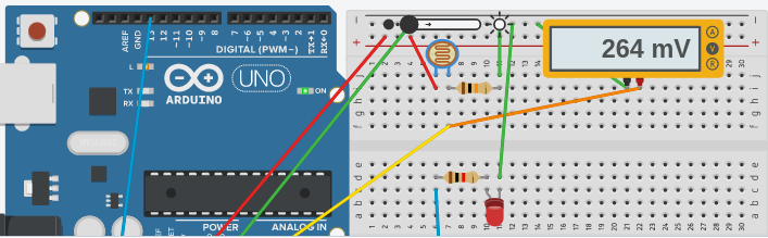
Now, let’s check the voltage drop under full light:
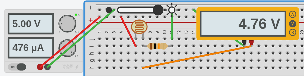
Here, we can see that we are dropping almost all of the voltage.
We need to decide on a threshold at which we want our LED to energize. Let’s say, we want the LED to energize when the voltage drop of the LDR falls below 1 volt.
Write the code
Here, we will use the Analog Input example which comes with your arduino software. Replace the code within the void loop() function as follows
Note: If this code gives you errors, type it manually. Sometimes by copying and pasting, you end up with some stray characters!
[sourcecode language="C++"]
int sensorPin = A0; // select the input pin for the potentiometer
int ledPin = 13; // select the pin for the LED
int sensorValue = 0; // variable to store the value coming from the sensor
void setup() {
// declare the ledPin as an OUTPUT:
pinMode(ledPin, OUTPUT);
}
void loop() {
// read the value from the sensor:
sensorValue = analogRead(sensorPin);
if (sensorValue < 200){
digitalWrite(ledPin,HIGH);
}else{
digitalWrite(ledPin,LOW);
}
}
[sourcecode]
Note: The value of 200 is about 1/5th of 1024 which would give us a threshold of around 1 volt.
Now let’s test our code during light conditions: You will notice the LED is OFF.
Then we will test the code under dark conditions: You will notice the LED is ON!
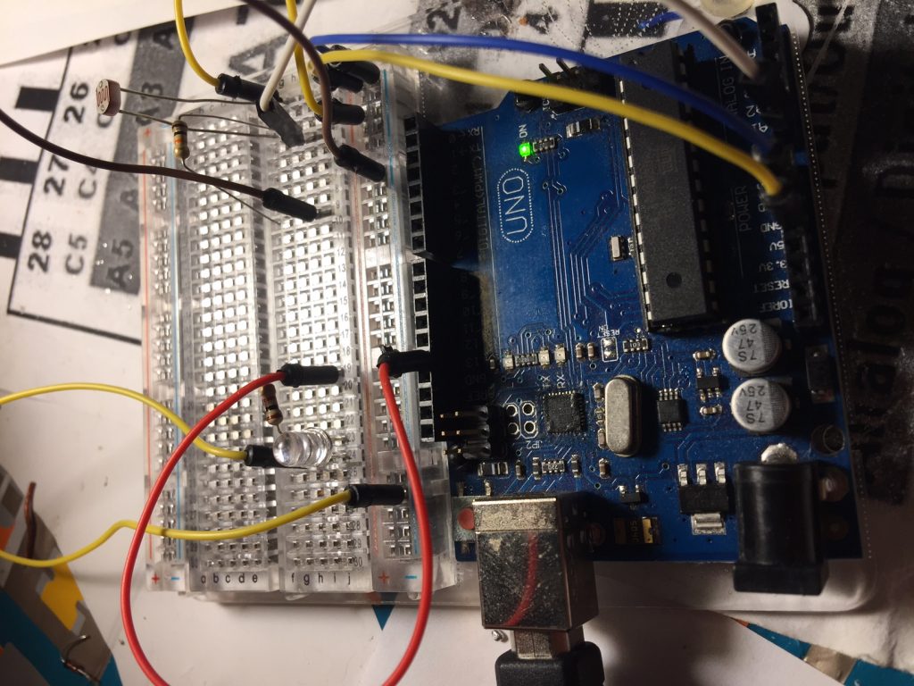
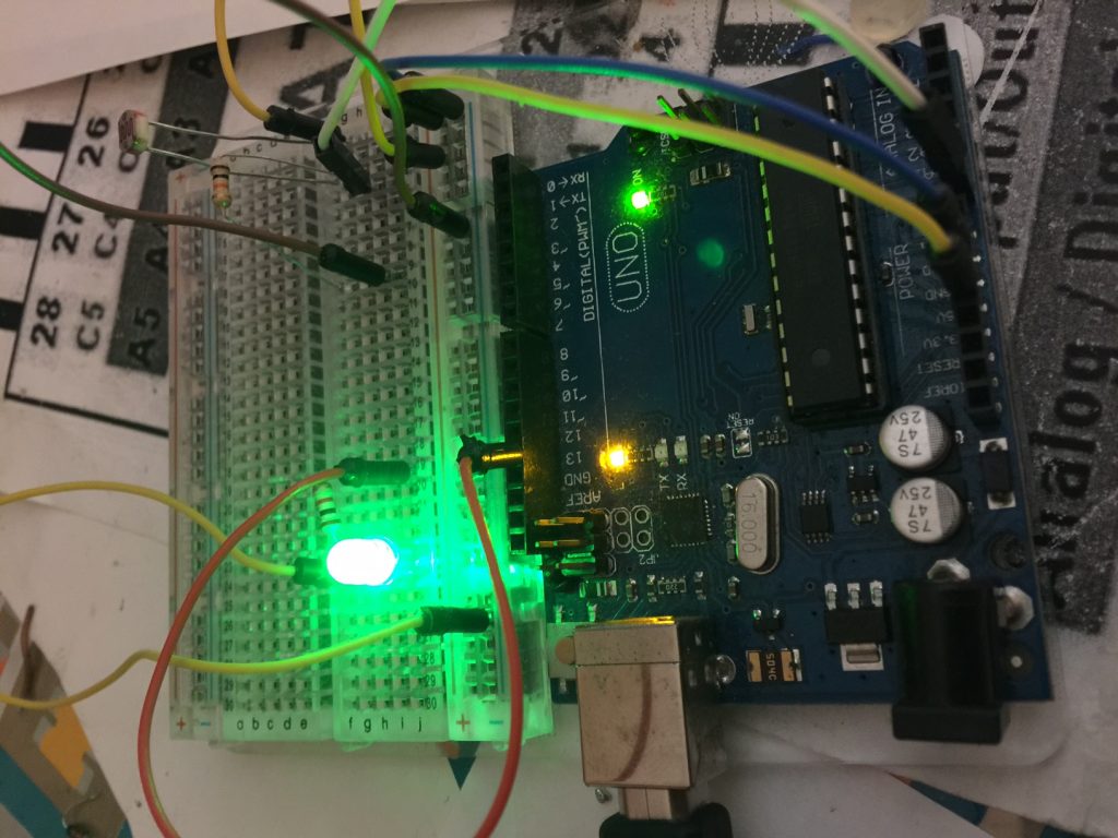
Let’s try this again in real life:
Lights On:
Lights Off:
Instead of just energizing a single LED indicator, you could energize a relay that will control a much larger load. It’s important to realize, however, that you are limited to about 20mA continuous current on the output pin. In this case, you would use a transistor such as the 2n2222, or 3904. Another key point is that a relay is inductive. This means that when you shut off the relay, you will produce a voltage spike. If you reverse bias a diode across the relay coil, you would eliminate this problem. The voltage spike will be in the opposite direction of the current normally flowing through the coil. You will hear terms like Snubber, Surge Suppressor, or Fly-back diode to describe the device suppressing the voltage spike from the coil.
For more information on basic components and projects, visit the beginner’s category page!
— Ricky Bryce